Electrical System Design

Cable Sizing & Voltage Drop

AS/NZS 3008.1.1 + AS/NZS 3000 project-based LV cable sizing workstation with a single-line diagram editor, multi-circuit projects, derating wizard, fault-loop Zs, cable I²t, AS/NZS 60898 discrimination, RCD coordination, max demand assessment, PV / DC compliance, IEEE 1584 arc-flash, and audit-grade provenance for every calculation.

Overview

Cable sizing in an Australian or New Zealand low-voltage installation is rarely a single calculation. A run that passes voltage drop can still fail its derated ampacity once ambient temperature and grouping are applied; a cable that carries its load comfortably can fail to clear an earth fault inside the AS/NZS 3000 disconnection time; a perfectly rated conductor can be cooked by the short-circuit energy let through before the protective device opens. The engineer who sizes against voltage drop alone, then discovers the derating, fault-loop, or thermal-endurance failure at inspection, pays for the mistake in re-work. The noIM₃ Cable Sizing & Voltage Drop workstation puts all of these checks in one place and ties every verdict back to the clause that produced it.

The workstation is built directly on the Australian / New Zealand wiring standards. Current carrying capacity, voltage drop, reactance, resistance, and short-circuit performance come from AS/NZS 3008.1.1:2009; protective earth conductor sizing, fault-loop disconnection time, RCD coordination, and maximum demand come from AS/NZS 3000:2018. PV and battery DC circuits are evaluated against AS/NZS 5033 and AS/NZS 4777.1, and arc-flash incident energy is computed to IEEE 1584-2018. Every published cable table the engine relies on — ampacity Tables 4 / 5 / 7 / 8 / 10 / 11 / 13 / 14 / 21, reactance Table 30, resistance Tables 34 / 35, derating Tables 22-29, and the short-circuit K constants of Table 52 — is transcribed directly from the standard and validated against its own worked examples.

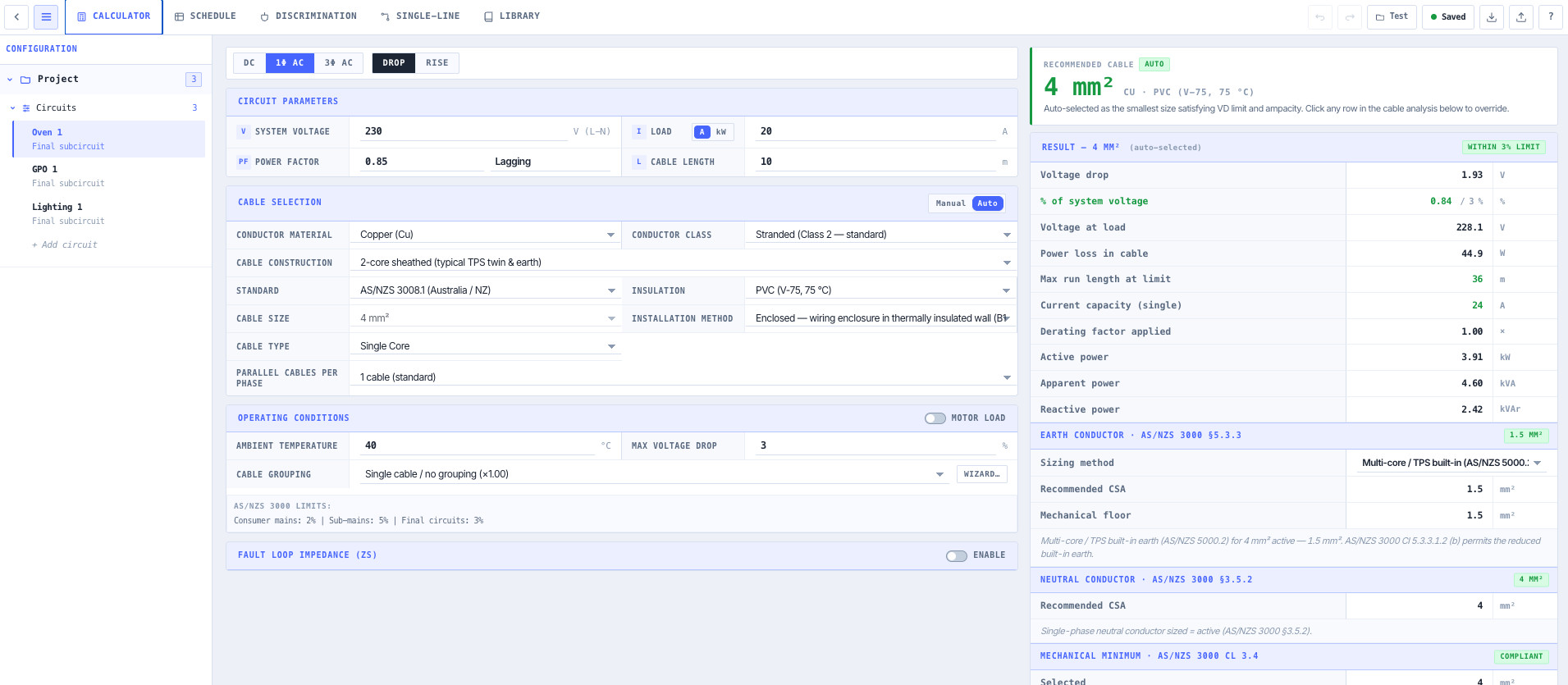
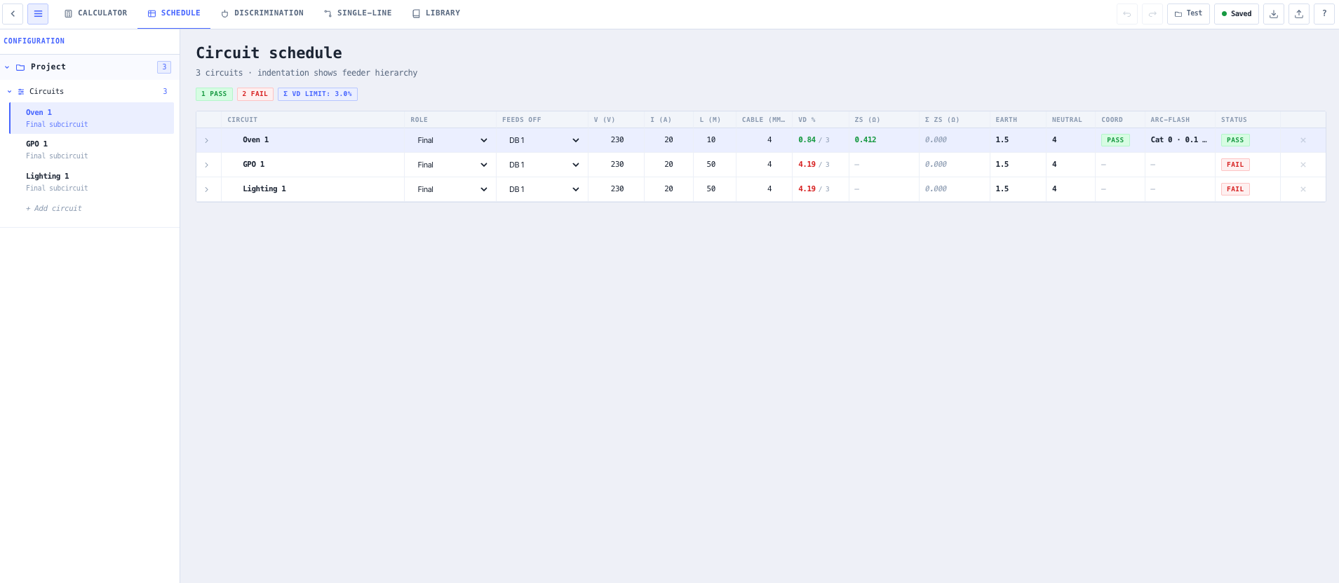
This is a project workstation, not a single-shot calculator. A project holds many circuits — consumer mains, sub-mains, final subcircuits, DC and PV feeders — and exposes a project picker, a multi-circuit project tree, an interactive single-line diagram editor with AS 3000 / IEC 60617 symbols, a cable schedule, a per-circuit calculator with a full derating wizard and fault-loop panel, a discrimination view with a log-log time-current curve chart, and an editable equipment library. Quick one-off cable checks and full LV distribution design coexist in the same model. Local autosave persists every change and JSON export round-trips the whole project for backup, peer review, or transfer between design teams.

Capabilities

AS/NZS 3008.1.1:2009 cable tables, fully transcribed

Every cable table the engine relies on is transcribed directly from the published standard and validated row by row against worked examples. Current carrying capacity Tables 4 (two single-core V-75 Cu), 5 (two single-core X-90 Cu), 7 and 8 (three single-core), 10 and 11 (two-core sheathed — typical TPS twin and earth), 13 and 14 (three / four-core sheathed — typical three-phase mains TPS), and 21 (aerial Al) back the ampacity lookups. Reactance Table 30 with the correct column per construction (trefoil, flat touching, multicore circular, shaped). Resistance Tables 34 and 35 for both Cu and Al at the 75 °C and 90 °C reference temperatures. Sizes 1 to 630 mm² are covered with the precision the standard publishes.

AS/NZS 3008.1.1 derating wizard, all rating factors

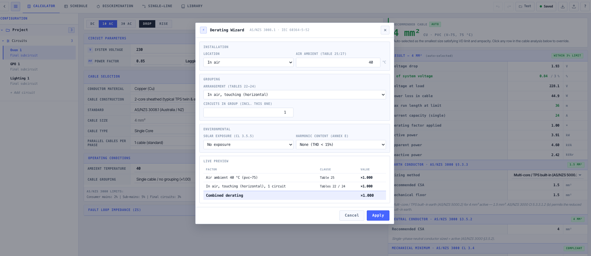
The derating wizard layers every published rating factor over the base ampacity, with the right column auto-selected for the cable construction and installation. Table 27(1) air and concrete-slab ambient and Table 27(2) soil ambient temperature; Table 28(1) burial depth (size-banded for ≤50, 50-300, and >300 mm²) and Table 28(2) underground enclosure; Table 29 soil thermal resistivity (five columns auto-picked); and Tables 22-26 grouping for bunched, on surfaces, in single layers, in trays, on ladders, and buried. Solar exposure and harmonic content factors complete the chain. The combined derating multiplier and each factor with its table citation are surfaced live for traceability.

Fault-loop Zs and AS/NZS 3000 disconnection time

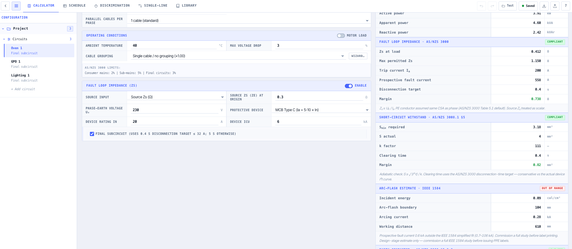
Toggle Fault Loop Impedance on and pick the input mode (source Zs in ohms or source fault level in kA). The engine sums source Zs with cable Zs through the cumulative parent chain, derives Zs(actual), and compares it against Zs(max) for the protective device's instantaneous trip current and the AS/NZS 3000 Table 8.1 maximum disconnection time (0.4 s for final subcircuits ≤ 32 A, 5 s for fixed wiring). Prospective earth-fault current is reported in amperes, and the same calculation feeds the cable thermal endurance check.

Cable thermal endurance, earth conductor, and arc-flash

Three further compliance verdicts derive from the prospective fault current. AS/NZS 3008.1.1 Clause 5.3 cable thermal endurance applies the adiabatic equation I²·t ≤ K²·S² with K constants from Table 52 (Cu/V-75 = 111, Cu/X-90 = 143, Al/V-75 = 74, Al/X-90 = 94, Cu/R-HF-110 = 132, among others). AS/NZS 3000:2018 Table 5.1 sizes the protective earth conductor (Cu and Al) with the adiabatic method as a secondary check, the larger of the two recommended. IEEE 1584-2018 surfaces a design-stage arc-flash estimate: incident energy in cal/cm², arc-flash boundary in mm, arcing current in kA, and PPE category at a 610 mm working distance.

Single-line diagram editor with AS 3000 / IEC 60617 symbols

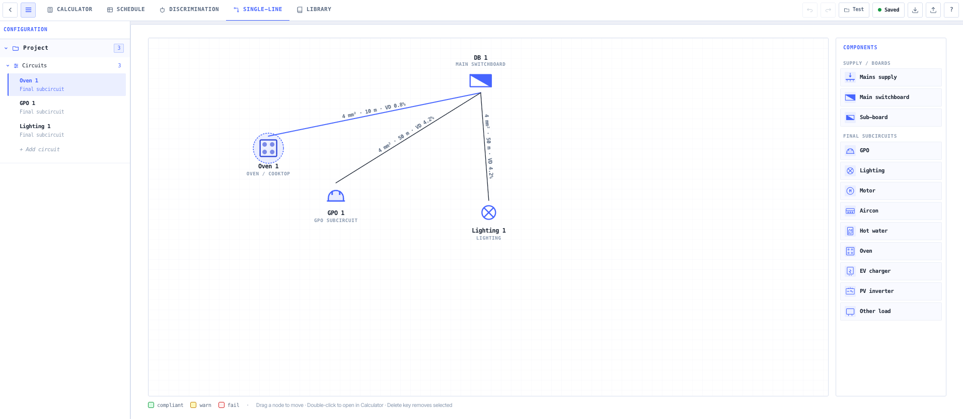
An interactive SLD editor renders each component as its AS 3000 / IEC 60617 symbol — mains supply, main switchboard, sub-board, GPO, lighting, motor, air-conditioning, water heater, oven, EV charger, PV inverter, and generic load. The canvas pans by click-and-drag on empty space and zooms by mouse wheel (0.25× to 4×, cursor-anchored). Components are placed free-floating and a cable only appears once two components are connected, so free-floating icons do not enter the schedule until wired. Cable labels rotate parallel to the line and cite size, length, and voltage drop percentage inline, and component name labels reposition automatically so cables never cross the text.

AS/NZS 60898 discrimination with time-current curves

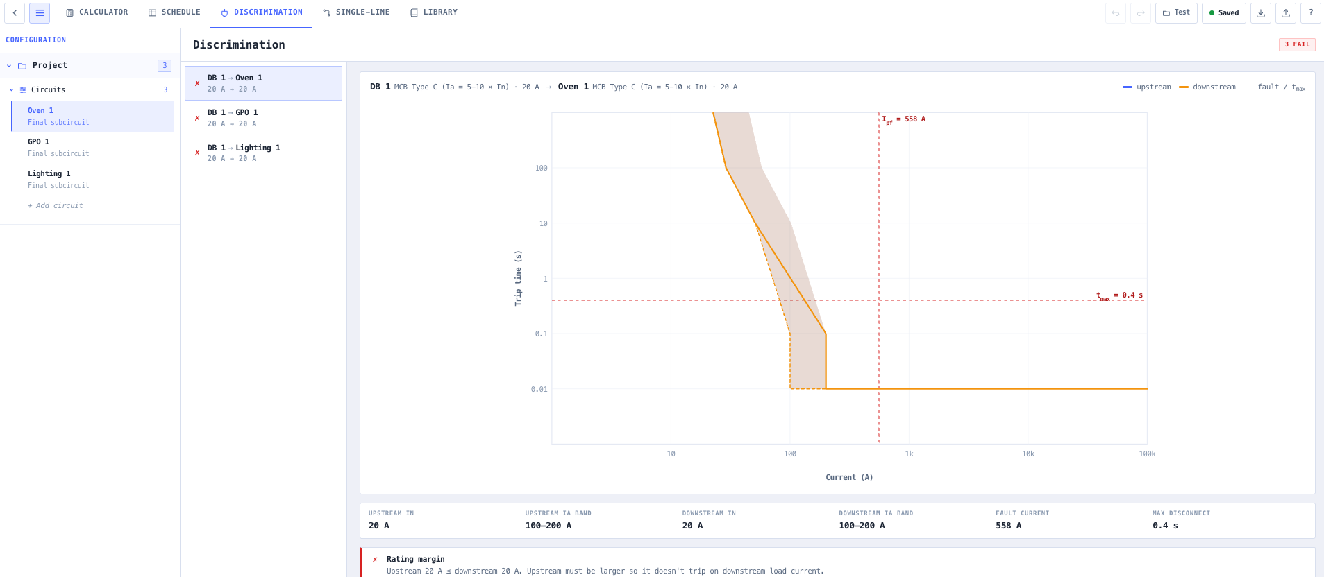
The Discrimination view walks every parent / child device pair and grades it against the AS/NZS 60898-1 / IEC 60898-1 Table ZA.1 magnetic trip bands (Type B 3-5×, Type C 5-10×, Type D 10-20×, Type K 8-12×, Type Z 2-3×) plus MCCB, ACB, and HRC fuse gG bands, AS/NZS 3000 §2.6.3 RCD coordination (upstream IΔn ≥ 3× downstream and S-type), and AS/NZS 3008.1.1 cable thermal endurance under the downstream fault. A master-detail layout pairs the device list with a full-width log-log time-current curve chart (1 A to 100 kA × 0.001 s to 1000 s) drawing the upstream and downstream trip envelopes as filled polygons, a fault-current marker, and the disconnection-time threshold overlay, with a per-check breakdown citing the clause behind every verdict.

AS/NZS 5033 + AS/NZS 4777.1 PV / DC compliance

PV strings, PV arrays, PV mains, and battery feeders are evaluated against the DC compliance envelope: AS/NZS 5033 Cl 4.3.5 cable rating ≥ 1.25 × Isc(STC), AS/NZS 5033 Cl 5.3.3.2 insulation voltage class ≥ 1.20 × Voc(STC), and the AS/NZS 4777.1 Section 7 voltage-drop ceilings (3 % string and array, 1 % inverter mains, 5 % total system). DC is treated as a single-loop topology with no power factor or three-phase coefficient.

Auto cable sizing against every constraint at once

Switch Sizing Mode to Auto and the engine sweeps the standard size ladder (1, 1.5, 2.5, 4, 6, 10, 16, 25, 35, 50, 70, 95, 120, 150, 185, 240, 300, 400, 500, 630 mm²) and returns the smallest size that simultaneously satisfies the voltage drop limit, the derated ampacity, the AS/NZS 3000 Table 8.1 disconnection time at the prospective fault, the AS/NZS 3008.1.1 short-circuit S_min, and the mechanical-strength floor for the role. The selected size flows into the cable selector with the binding constraint cited.

Multi-circuit project model with autosave and JSON round-trip

Projects hold many circuits, each with its own cable selection, derating chain, fault-loop configuration, and protection device. The schema separates quick circuits (added directly via the schedule for one-off checks) from SLD-bound circuits (cable runs between connected components), so spot calculations and full LV distribution design live in one workstation. Every change autosaves to local storage, and JSON export produces a versioned, human-readable .vd.json file that round-trips back through the project picker, preserving every circuit, position, derating setting, and library override.

Standards & methodology

  • AS/NZS 3008.1.1:2009 — selection of cables (current carrying capacity, voltage drop, short-circuit performance)
  • AS/NZS 3000:2018 — the wiring rules (earth conductor Table 5.1, disconnection time Table 8.1, RCD coordination §2.6.3, max demand Appendix C Table C1)
  • AS/NZS 60898-1 / IEC 60898-1 — magnetic trip bands Table ZA.1 (Type B / C / D / K / Z)
  • AS/NZS 5033 — PV array installation (Cl 4.3.5 cable rating ≥ 1.25 × Isc, Cl 5.3.3.2 insulation ≥ 1.20 × Voc)
  • AS/NZS 4777.1 — grid-connected inverter energy systems (Section 7 voltage-drop limits)
  • AS/NZS 3013 — high-temp R-HF-110 / X-HF-110 fire-rated cabling slot
  • IEC 60364-5-53 — RCD selectivity rule applied to AS/NZS 3000 §2.6.3 coordination
  • IEEE 1584-2018 — arc-flash incident energy
  • IEC 60617 — single-line diagram graphical symbols (with AS 3000 symbols)

When to use this tool

  • Sizing a single cable run with AS/NZS 3008.1.1 ampacity and voltage drop verification
  • Designing a full LV distribution from consumer mains down through sub-mains to final subcircuits
  • Verifying an existing installation against AS/NZS 3000 disconnection time and earth-conductor sizing requirements
  • Coordinating cascaded MCB / MCCB / RCD protection across a switchboard hierarchy
  • Producing a cable schedule (cable bill of quantities) for a tender package or commissioning hand-over
  • Assessing maximum demand on a sub-main per AS/NZS 3000 Appendix C single-domestic diversity factors
  • Sizing PV array / string / mains DC cables per AS/NZS 5033 and AS/NZS 4777.1 voltage-drop targets
  • Auto-sizing a cable to the smallest compliant size against VD, ampacity, Zs, S_min, and mechanical floor simultaneously
  • Estimating arc-flash incident energy at a switchboard for a design-stage PPE selection (commission a full IEEE 1584 study before labelling)
  • Validating a vendor-supplied cable schedule against AS/NZS 3008.1.1 derating with the published rating-factor chain
  • Producing single-line diagrams with AS 3000 symbols for permit applications or installation drawings
  • Round-tripping a project through JSON for peer review, archival, or transfer between design teams

Is this the right tool for you?

Reach for the Cable Sizing & Voltage Drop in any of the following situations.

  • You have sized a sub-main against voltage drop and need to confirm it still passes once the derating wizard applies the soil ambient, burial depth, thermal resistivity, and grouping factors.
  • You need to prove a final subcircuit clears an earth fault inside the AS/NZS 3000 Table 8.1 0.4 s disconnection time, with Zs(actual) summed through the parent chain.
  • You are checking that the cable survives the short-circuit energy let through by its protective device using the AS/NZS 3008.1.1 Clause 5.3 I²·t ≤ K²·S² endurance check.
  • You have cascaded MCBs on a switchboard and need to confirm the downstream trip band sits entirely below the upstream band on the time-current curve chart.
  • You are coordinating upstream and downstream RCDs and need to confirm the AS/NZS 3000 §2.6.3 selectivity rule (upstream IΔn ≥ 3× downstream and S-type) is satisfied.
  • You are sizing a PV string and array DC cable and need it rated to ≥ 1.25 × Isc with insulation ≥ 1.20 × Voc and within the AS/NZS 4777.1 voltage-drop ceilings.
  • You want the engine to auto-size a cable to the smallest standard size that simultaneously satisfies VD, derated ampacity, disconnection time, S_min, and the mechanical floor.
  • You are assembling a cable schedule for a tender package and need one row per cable with per-row compliance and aggregate pass / warn / fail counts.
  • You are drawing a single-line diagram with AS 3000 / IEC 60617 symbols for a permit application and need each connected run to become a sized cable circuit.
  • You need a design-stage arc-flash estimate at a switchboard to inform PPE selection, knowing a full IEEE 1584 study is still required before labelling.
  • You are handing a project to another engineer and need to export it to a versioned, human-readable .vd.json that round-trips back through the project picker.
  • You are assessing maximum demand on a single-domestic sub-main using the AS/NZS 3000 Appendix C Table C1 diversity factors.

Frequently asked questions

Which standards does the cable sizing actually use?

Current carrying capacity, voltage drop, reactance, resistance, and short-circuit performance come from AS/NZS 3008.1.1:2009. Protective earth conductor sizing (Table 5.1), fault-loop disconnection time (Table 8.1), RCD coordination (§2.6.3), and maximum demand (Appendix C) come from AS/NZS 3000:2018. PV and battery DC circuits are evaluated against AS/NZS 5033 and AS/NZS 4777.1, discrimination against AS/NZS 60898-1 / IEC 60898-1, and arc-flash against IEEE 1584-2018. Every value the engine produces is traceable to the specific clause that produced it.

How does the derating wizard work?

It layers every published AS/NZS 3008.1.1 rating factor over the base ampacity, with the right column auto-selected for the cable construction and installation: air or soil ambient temperature (Table 27), burial depth (Table 28, size-banded), soil thermal resistivity (Table 29, five columns auto-picked), grouping for bunched / surface / single-layer / tray / ladder / buried installations (Tables 22-26), plus solar exposure and harmonic content factors. The combined derating multiplier and each individual factor are surfaced live with their table citation for traceability.

What does the fault-loop check verify?

You provide the source either as Zs in ohms or as a source fault level in kA. The engine sums source Zs with cable Zs through the cumulative parent chain, derives Zs(actual), and compares it against Zs(max) for the protective device's instantaneous trip current and the AS/NZS 3000 Table 8.1 maximum disconnection time — 0.4 s for final subcircuits up to 32 A, 5 s for fixed wiring. It reports the prospective earth-fault current in amperes, which also feeds the cable thermal endurance check.

How is the short-circuit cable thermal endurance checked?

The engine applies the AS/NZS 3008.1.1 Clause 5.3 adiabatic equation I²·t = K²·S² with K constants transcribed exactly from Table 52 — for example Cu/V-75 = 111, Cu/X-90 = 143, Cu/R-HF-110 = 132, Al/V-75 = 74, Al/X-90 = 94. It confirms the conductor survives the fault energy let through by the protective device. The verdict appears as a per-circuit result in the Calculator and as a check row in the Discrimination view for each cascaded pair.

What does Auto sizing mode do?

Auto mode sweeps the standard size ladder from 1 mm² to 630 mm² and returns the smallest size that simultaneously satisfies the voltage drop limit, the derated ampacity, the AS/NZS 3000 Table 8.1 disconnection time at the prospective fault, the AS/NZS 3008.1.1 short-circuit S_min, and the mechanical-strength floor for the role. The selected size flows into the cable selector and the binding constraint is cited so you know which check governed the result.

Can it handle PV and battery DC circuits?

Yes. PV strings, PV arrays, PV mains, and battery feeders are evaluated against the DC compliance envelope: AS/NZS 5033 Cl 4.3.5 cable rating ≥ 1.25 × Isc(STC), AS/NZS 5033 Cl 5.3.3.2 insulation voltage class ≥ 1.20 × Voc(STC), and the AS/NZS 4777.1 Section 7 voltage-drop ceilings of 3 % for string and array, 1 % for inverter mains, and 5 % for the total system. DC is modelled as a single loop with no power factor or three-phase coefficient.

How is the arc-flash result intended to be used?

The Calculator surfaces an IEEE 1584-2018 arc-flash estimate per circuit — arcing current, incident energy in cal/cm² at a 610 mm working distance, arc-flash boundary in mm to the 1.2 cal/cm² limit, and the corresponding PPE category. It is explicitly a design-stage estimate, and the panel advises that a full IEEE 1584 study should be commissioned before issuing PPE labels.

How are projects saved and shared?

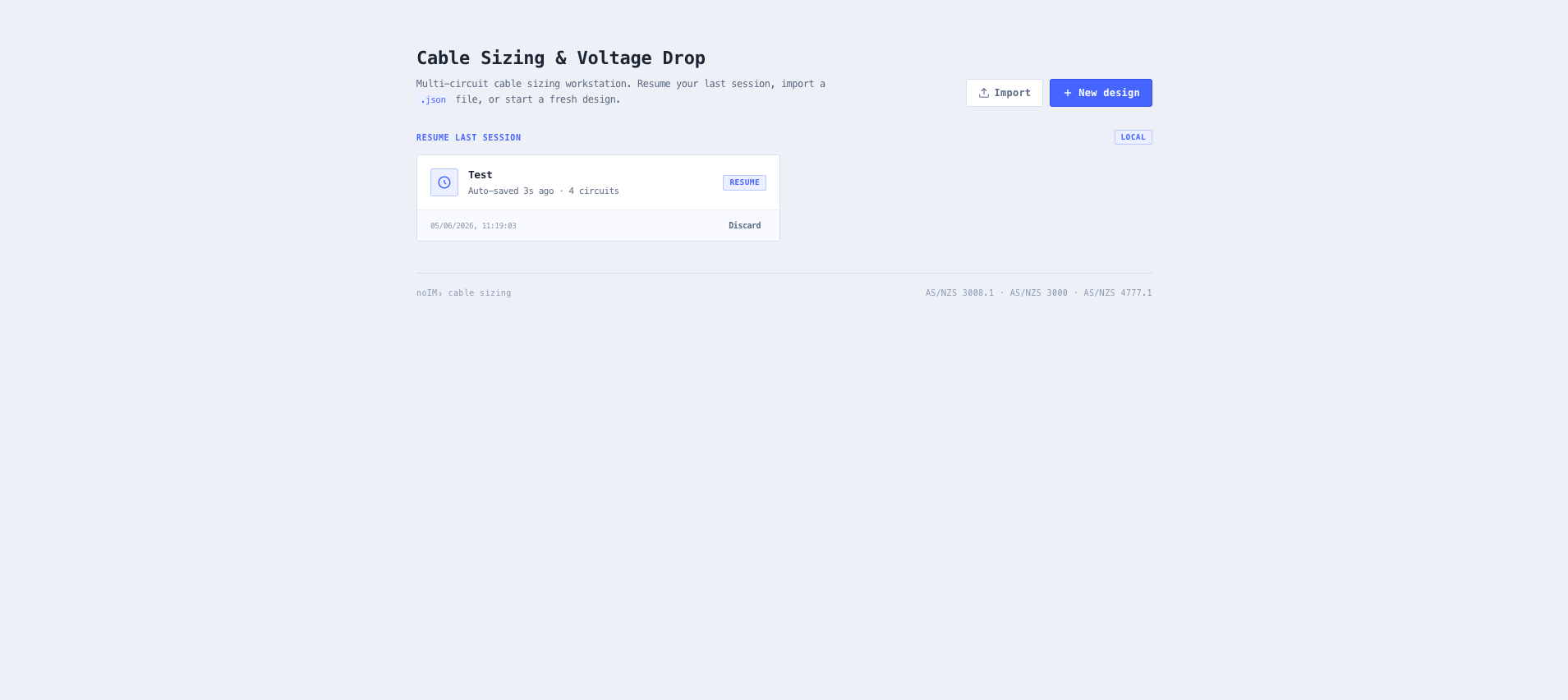
Every change autosaves continuously to local storage, so an unsaved session is recoverable from the project picker without an explicit save. Export produces a versioned, human-readable .vd.json snapshot containing every circuit, cable selection, derating setting, protection device configuration, SLD position, and library override. The file round-trips back through Import for backup, peer review, transfer between engineers, or staging in source control alongside the rest of the design package.