CCTV

CCTV Camera Placement Designer

Place cameras on a scaled site plan or a satellite map, in 2D and 3D, and see the coverage they actually deliver in px/m

Included in the 14-day Pro trial on every new account. No credit card.

Overview

Most camera layouts are argued with a coverage cone drawn over a floor plan. That drawing answers the wrong question. It shows where a camera is pointed, not whether the picture at a given spot carries enough pixels across a face to identify somebody, and it quietly assumes the camera can see through the building.

This tool works in pixel density. For every point it computes how many pixels fall across a metre of a vertical target at that distance, from the camera's real horizontal field of view and its recorded image width. That is the quantity the DORI criteria are stated in and the quantity a client specification is written against, so a requirement reads as "this area needs Recognise, which is 125 px/m" and the plot either meets it or it does not.

Line of sight is tested against the walls you draw, in three dimensions. A wall blocks a camera only where the sightline actually passes through it, so a 1.1 metre balustrade in front of a camera mounted at 3.5 metres casts no shadow, while the same rail blocks the same camera aimed at the floor beside it. Glazing and open doorways stay transparent; mesh and tinted glass are reported as degraded rather than being either ignored or treated as solid.

The same design works on a plan, on satellite imagery and in 3D, because the engine computes in local metres and those are three renderers rather than three implementations. A layout started on an imported PDF can be pinned to its real location afterwards without anything moving.

Pixel density on its own is not the whole answer, so the tool checks the things that make a nominally compliant picture useless. A number-plate zone is tested against the angle a plate can actually be read from, because a plate is a flat panel and a camera looking at it from the side is counting pixels across characters it cannot resolve. A PTZ is not credited toward any requirement until it has been parked on a view, because a camera that can be driven elsewhere is not holding anything. Assess the design at night and every camera is credited only as far as there is light, which is its own reach where the ambient is enough and its illuminator reach where it is not.

Capabilities

Pixel density, not a coverage cone

Coverage is computed as px/m on a vertical target at slant range, which is what the DORI criteria are expressed in. A cone tells you where a camera points; px/m tells you whether the picture is good enough for what the area needs.

Line of sight against real wall heights

Every sample point is tested against the walls and fences you draw, and each carries a height and an underside. A balustrade, a low partition and a full-height wall behave differently, which is the difference between a shadow the site has and one it does not.

Openings that actually open

Doors, windows and gates are cut into a wall and take their own opacity, so a camera sees down an open corridor and through a shopfront. A sightline passing above a door head still meets the wall, which surprises people and is exactly right.

The blind spot under the camera

A tilted camera cannot see the ground below itself. The near edge follows from mounting height, tilt and vertical field of view, and it is drawn. It is the most common surprise on a commissioned system and the one a plan-view cone hides completely.

PDF and image plan import

Bring in a floor plan or site layout as a PDF, choosing the page, or as a photograph of a drawing. Scale it by clicking two points of known separation, or by dragging it onto a grid of known pitch when the drawing carries no dimension at all.

Field of view from real optics

A datasheet angle is used as printed. Where only a focal length and sensor format are given the angle is derived and labelled as derived, with a warning past the point where the rectilinear assumption stops holding.

Generic library plus the component catalogue

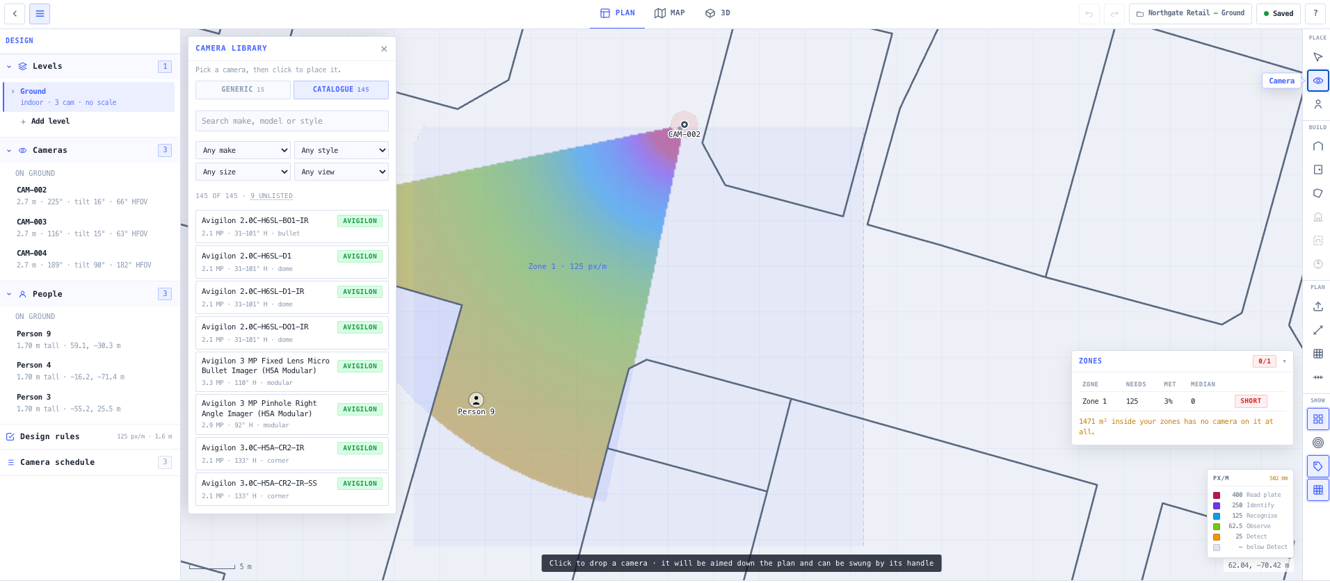
A generic library of the common resolution and lens classes is the default path, so the tool is complete before a model is chosen. Catalogue models hydrate the same interface, and a camera whose optics cannot be read is offered with the optics left to you rather than invented.

Zones carry the requirement

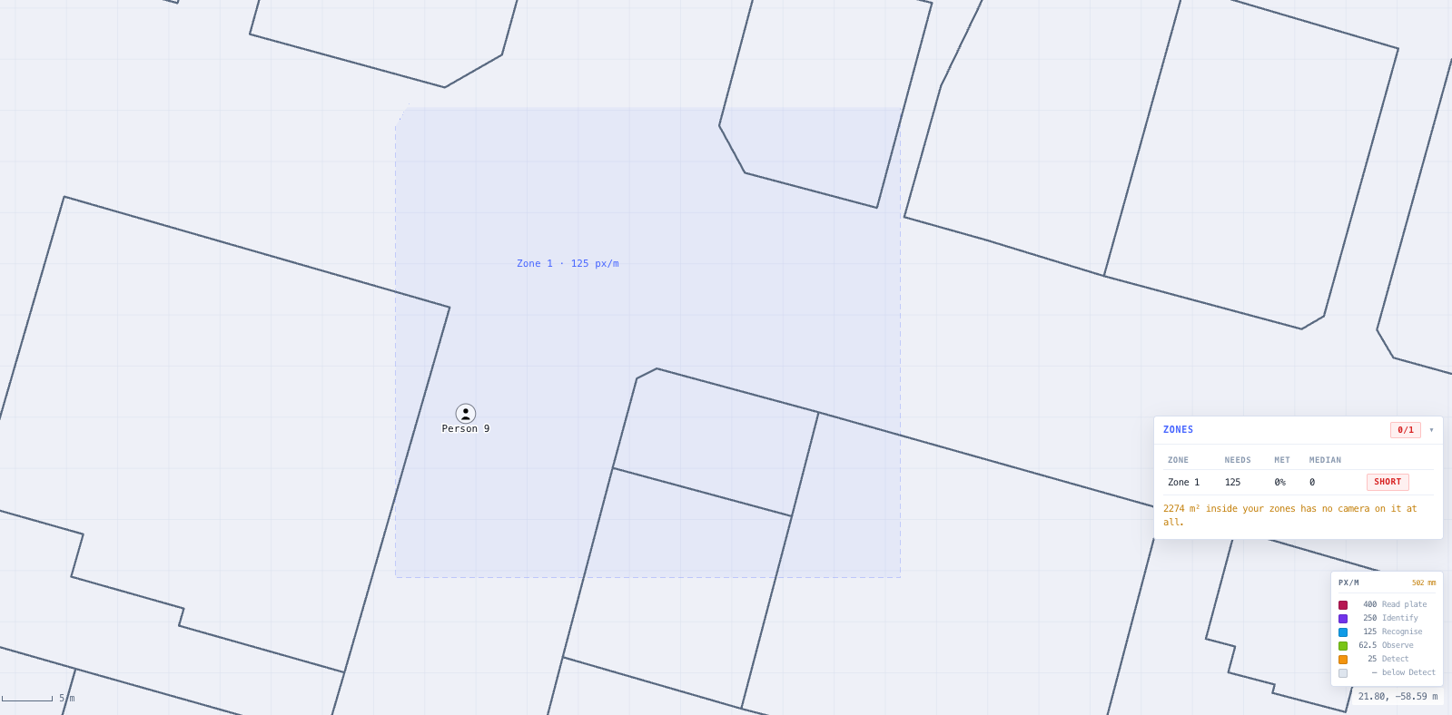
Draw the areas the design will be judged on and give each its own px/m target. Statistics are reported per zone against that zone's requirement, because a design is signed off area by area and a site-wide percentage says nothing about which part failed.

Plan, satellite map and 3D

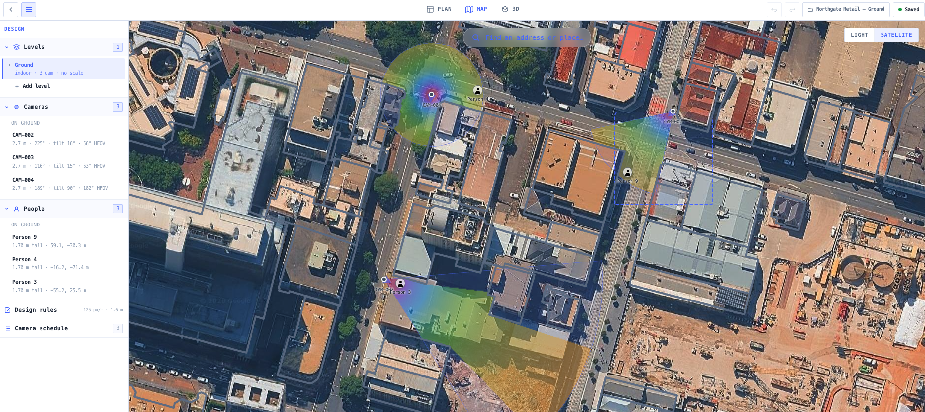
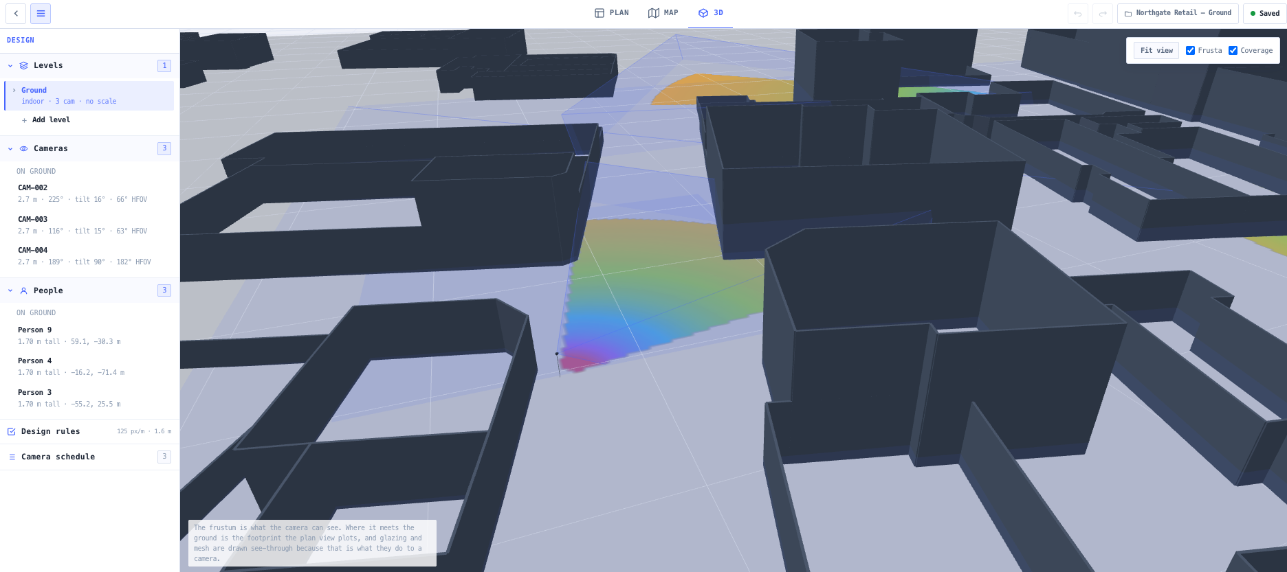
Pin the design to a location and the same cameras, walls and coverage appear over satellite imagery. The 3D view shows each frustum against walls at their real heights, where a marginal sightline becomes obvious.

Number-plate work is judged on angle, not just pixels

A plate is a flat panel facing one way. Seen from the side its characters foreshorten, and a reflective plate stops returning the infrared an illuminated camera depends on. A plate-read zone is checked against how far round from the plate the camera sits and how far above it, and reports what can be read next to what merely has the pixels.

A PTZ is not coverage until you park it

A camera that can be driven somewhere else is not holding a requirement. A PTZ is drawn, scheduled, powered and cabled as normal, but it is not credited toward any zone until it is parked on a view. Zones served by one show both figures, so you can see what the fixed cameras hold and what the PTZ would add.

Night, infrared reach and lens aperture

Assess the design at night and each camera is credited only as far as there is light. Ambient light does not limit range because a lit yard is lit at every distance, but an illuminator does, and its reach changes with zoom. Sensitivity figures are corrected for the aperture in use, since light at the sensor goes as one over the f-number squared.

Fisheye and 360 modelled as what they are

A fisheye is not a wide rectilinear lens. Its image is a disc and its projection maps angle evenly onto the sensor rather than through a tangent, so the ground it covers is an arc and not a chord. Modelled properly, which is why a ceiling fisheye here covers the full circle its part number advertises.

A report that states its own limits

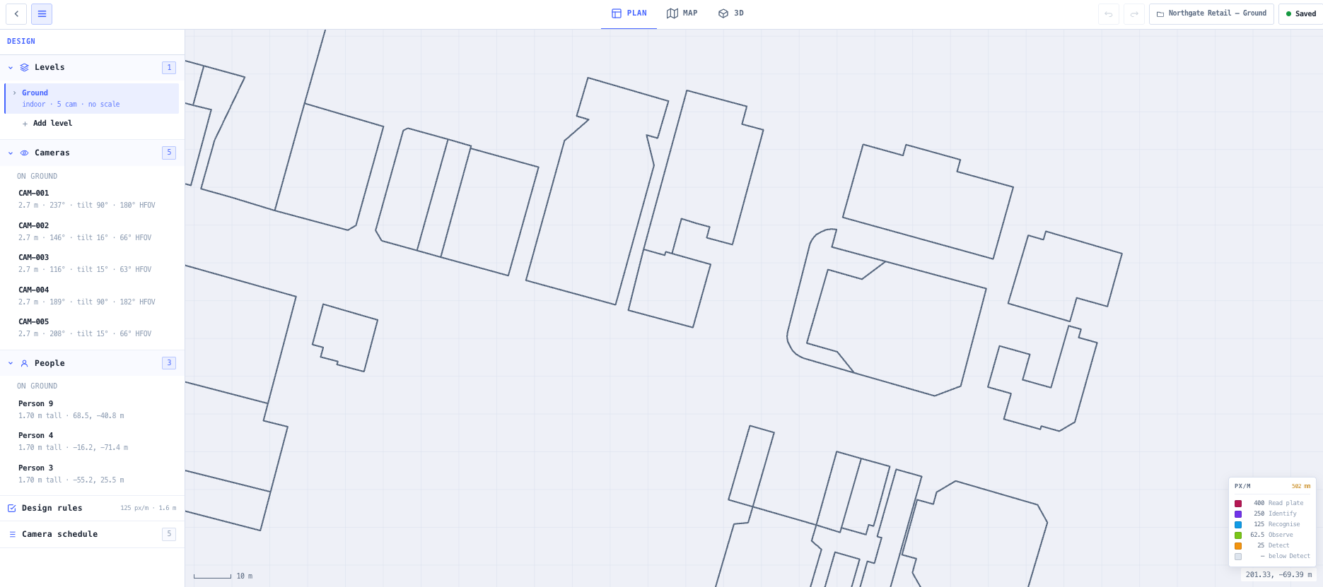
The plan drawn to scale, the camera schedule, the result for every zone, and a plain list of what was not assessed. An unscaled plan is called out at the top, because it makes every distance in the document a guess.

Standards & methodology

  • IEC/EN 62676-4 DORI criteria, as commonly published
  • IEEE 802.3af / at / bt for PoE classes
  • WGS-84 for the map projection
  • Number-plate viewing angles follow common ANPR siting practice and are editable. They are not from EN 62676-4, which describes people and does not cover plate work
  • Minimum illumination figures are the manufacturer's own and are not comparable between manufacturers

When to use this tool

  • Proving a retail layout meets an Identify requirement at the tills
  • Checking perimeter coverage on a yard or depot before the fence line is fixed
  • Sizing number-plate capture on a car park entry lane
  • Finding the columns, plant and balustrades that will shadow a warehouse
  • Answering a client specification written in px/m or in DORI terms
  • Deciding between a multisensor on a corner and three fixed cameras
  • Setting mounting heights that avoid a blind spot over a doorway
  • Working out whether a corridor needs one camera or two at a given lens
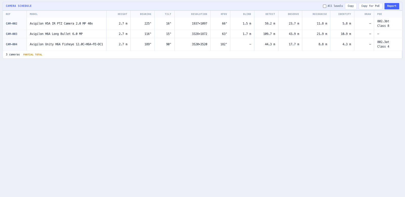
  • Producing a camera schedule that feeds bandwidth, storage and PoE sizing
  • Showing a client where their budget stops delivering recognition
  • Reviewing an installed system against what it was supposed to cover
  • Issuing a coverage report for a tender or a handover pack
  • Checking a number-plate lane is readable rather than merely well covered
  • Deciding whether a PTZ needs backing with a fixed camera or parking on a preset
  • Working out which cameras stop earning their keep after dark
  • Choosing between an illuminator and site lighting on an unlit boundary

Is this the right tool for you?

Reach for the CCTV Camera Placement Designer in any of the following situations.

  • A shopping centre tenancy needs Identify at every till and Recognise across the floor. You import the tenancy plan, scale it off a dimensioned wall, draw the counter line and the glazed shopfront, then place 4 MP varifocal domes and watch the Identify band contract as you widen the lens. The zone table tells you which tills are short before anybody quotes for the job.
  • A logistics yard needs detection along a 300 metre boundary. You pin the site to satellite imagery, trace the palisade fence, and find that the mesh is credited at Detect only, which is the honest answer and changes where the cameras go.
  • A car park entry lane needs plate capture. You set a zone target above Identify, place an 8 MP telephoto bullet, and use the DORI rings along the boresight to find the ten metre window where the plate is actually readable.
  • A refurbished office has a 1.1 metre glass balustrade around an atrium. On a plan-only tool it reads as a wall and blanks out half the floor below. Here it blocks nothing for the ceiling cameras and blocks a camera aimed at the floor beside it, which is what happens on site.
  • A gatehouse lane is specified for plate capture and the plot looks comfortable, but the camera is on a six metre pole four metres back. The zone reports that the pixels are all there and none of it is readable, because the camera is looking down on the plate at fifty degrees. Lowering it and setting it back down the lane fixes a problem that a density plot alone would have signed off.
  • A yard is covered by two fixed cameras and a PTZ on a tour. The zone table credits the fixed pair only and shows what the requirement would be if the PTZ were pointed that way, so the choice between parking the PTZ on a preset and adding a fixed camera is made on the numbers rather than on optimism.
  • A depot boundary is unlit. Switching the assessment to night cuts every camera back to its infrared reach, and half the boundary that read as covered in daylight goes dark. The report names the cameras relied on past their own light, which is the argument for either site lighting or a different camera.
  • A handover pack needs a coverage report. You issue the PDF with the plan drawn to scale, the schedule, the per-zone result, and the limitations section stating plainly that pixel density is a geometric quantity and says nothing about low light or motion blur.

Frequently asked questions

What is pixel density and why not just draw a coverage cone?

Pixel density is how many recorded pixels fall across a metre of a target at its distance from the camera. A coverage cone shows where a camera points but says nothing about whether the picture there is good enough to recognise anybody, and it assumes the camera can see through walls. Pixel density is the quantity the DORI criteria and most client specifications are written in.

Which DORI figures does it use?

Detect 25 px/m, Observe 62.5, Recognise 125 and Identify 250, which are the criteria as commonly published for IEC/EN 62676-4, plus an editable band for number-plate work. This tool has not transcribed the standard text and does not quote a clause, and every threshold can be overridden per zone when a client specification differs.

Does it take walls into account, or is it a free-space calculation?

It tests line of sight against the walls and fences you draw, in three dimensions. A wall carries a height and an underside, and it blocks a camera only where the sightline actually passes through it. Doors, windows and gates take their own opacity, so a camera sees through clear glazing and down an open corridor.

Do I have to draw the whole building?

No. Draw only the walls that will actually get in a camera's way. Anything you do not draw is treated as clear line of sight, and the report says so explicitly rather than implying the building was modelled.

Which cameras can I use?

A generic library covering the common resolution, sensor and lens classes, so you can lay a design out before choosing a model, plus the models in the noIM3 component catalogue whose datasheet optics can be read. A camera whose optics cannot be read is offered with its optics left to you rather than filled with a guess.

What if my camera is not in the catalogue?

Type its figures in. The engine consumes a field of view, a recorded image size and a mounting position; where those came from is recorded and shown, but no part of the tool requires a catalogue row to exist.

Can I use a PDF of a floor plan?

Yes. Choose the page and it renders at a resolution that stays crisp when you zoom in on a doorway. Scale it either by clicking two points whose real separation you know, or by dragging it onto a grid of known pitch when the drawing carries no dimension.

Does it work without a site plan?

Yes. You can draw straight onto the metric grid, or pin the design to satellite imagery and work over that. The plan is a backdrop, not a requirement.

Does a coverage figure mean the system will actually identify somebody?

Not on its own, and the tool checks more than the pixels. A design assessed at night credits each camera only as far as there is light. A plate-read zone is tested against the angle the plate can be read from. A PTZ is not counted until it has been parked on a view. What is still decided on site and not modelled here is image quality: backlight, focus, compression, lens distortion and the state of the dome. Pixel density remains a necessary condition rather than a sufficient one, and the report says so.

Why does my number-plate zone say the pixels are there but nothing is readable?

Because a plate is a flat panel and pixel density says nothing about the angle it is seen from. Off to one side the characters foreshorten by the cosine of the angle, and a reflective plate stops returning the infrared an illuminated camera relies on at night. The zone is checked against how far round from the plate the camera sits and how far above it, and the gap between what has the pixels and what can be read is usually a camera mounted too high and too close. Both limits default to thirty degrees and are editable.

Why is my PTZ not counted toward a zone?

Because it can be driven somewhere else. A PTZ is one camera that can be pointed at many places and is looking at exactly one of them, so a requirement met by a PTZ on a tour is met only while nobody has moved it. Tick Parked on this view when the design commits it to a fixed preset with the tour disabled, and it is credited exactly like a fixed camera. Zones served by an uncommitted PTZ report both figures so you can see what it would add.

Does it model low light and infrared?

Yes. Set the assessment to night and state the site illuminance, and each camera is credited only as far as there is light. Ambient light does not limit range, because a lit car park is lit at five metres and at fifty alike, but an illuminator does, and its reach grows as the lens zooms in because the same emitter power goes into a narrower beam. Sensitivity figures are corrected for the aperture in use, since light at the sensor goes as one over the f-number squared.

Can I compare cameras on their minimum illumination figures?

No, and the tool will not do it for you. There is no common test: manufacturers pick their own reference level, their own gain and their own shutter, and a slow shutter buys a smaller number at the cost of smearing anything that moves. Two rows quoting the same lux figure are not making the same claim. The figures are used only to ask whether one camera has enough light on one site, which is a question its own datasheet can answer. For the same reason a claim of zero lux with infrared is treated as a statement about the illuminator and never as a sensitivity.

How are fisheye and 360 cameras handled?

As what they are. A fisheye is not a very wide ordinary lens: its projection maps angle evenly onto the sensor rather than through a tangent, and its image is a disc rather than a rectangle. The ground it covers is an arc, not a chord, which is why a ceiling fisheye here covers the full circle its part number advertises instead of the wedge a rectilinear formula would produce.

How are thermal cameras handled?

Their geometry is modelled and their footprint is drawn, but the DORI bands above Detect are not applied to them. A thermal sensor detects a person at long range and cannot recognise or identify a face at any range, and the tool states that rather than scoring them on a scale they cannot meet.

Does the camera schedule feed the other CCTV tools?

The schedule exports in the shape the CCTV Bandwidth and NVR Storage Calculator and the PoE Power-Budget Planner work in, carrying resolution, frame size, head count, power and PoE class. It deliberately carries no bitrate: that depends on codec, scene and encoder, and the storage calculator models it properly from these inputs.

Where are my plan images stored?

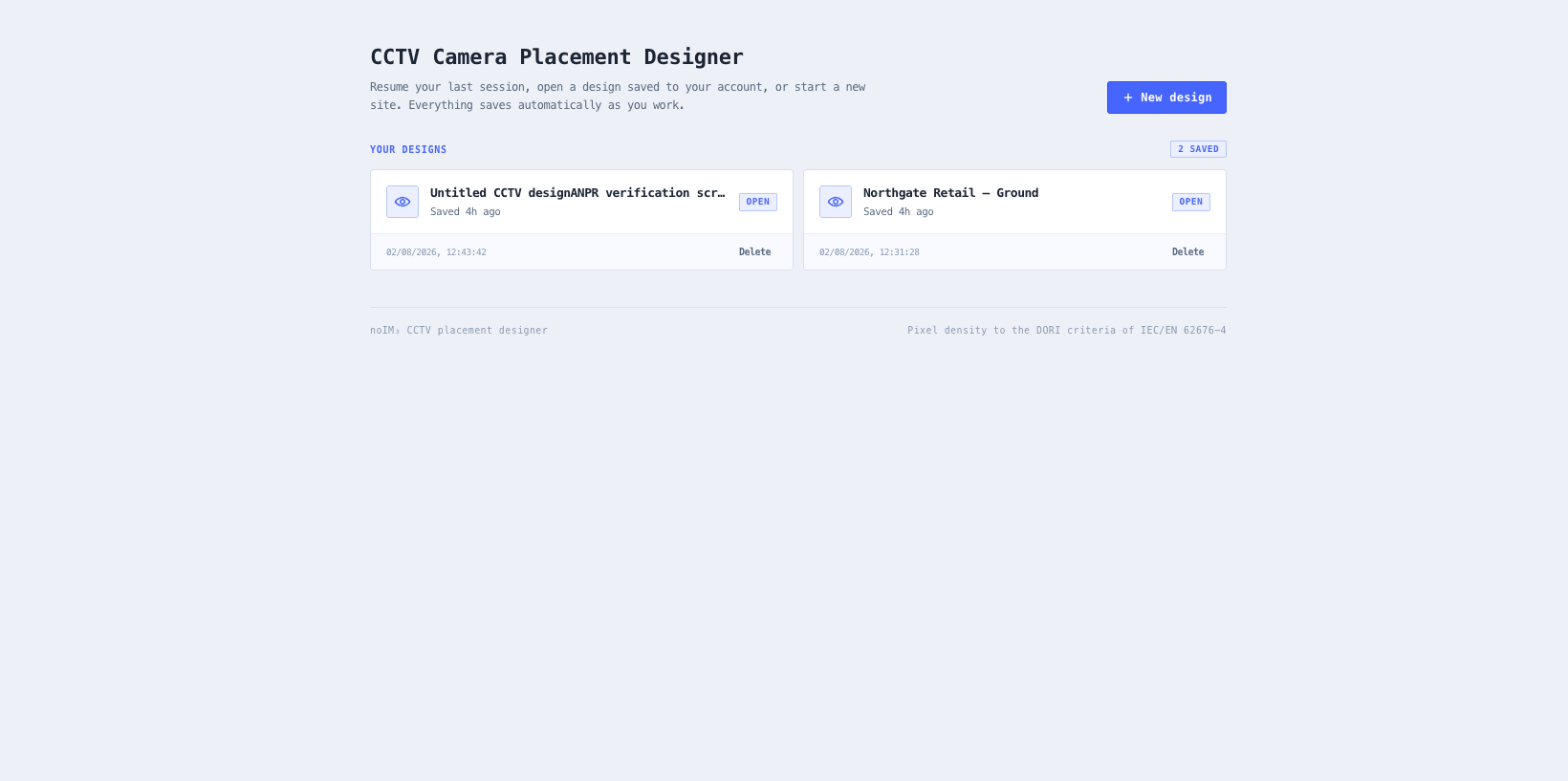
On the device that imported them. The design itself, including every wall, camera, zone and scale, syncs to your account and opens anywhere you sign in. The images stay local because a multi-level project would otherwise exceed the payload limit, so opening a design on another machine keeps the whole design and asks you to re-import the drawing.