Microwave Link Planning

Point to Point Link Planner

ITU anchored RF link planning workstation for point to point and point to multipoint design, with terrain accurate path profiles, full ITU model coverage, and audit grade provenance for every number.

Overview

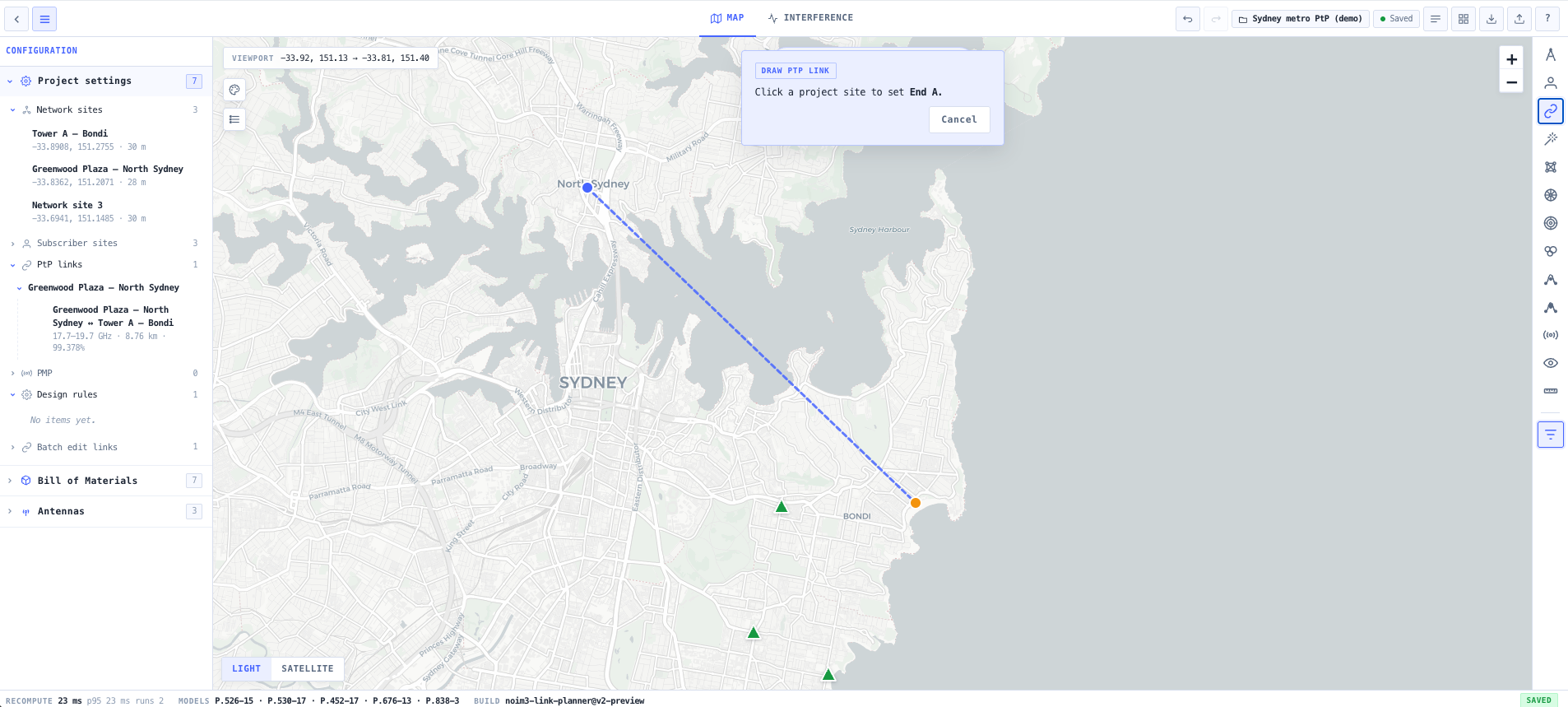
A microwave point to point link looks deceptively simple on paper. Two sites, a clear line of sight, a frequency, an antenna at each end. In practice, getting from a site survey to a link that actually meets its availability target involves terrain modelling, Fresnel zone clearance, atmospheric absorption, rain attenuation, multipath fading, diversity gain, antenna pattern matching, regulatory channel selection, and a coordination check against incumbents. Skip any one of these and the link either fails to perform on the day, or fails coordination during licensing.

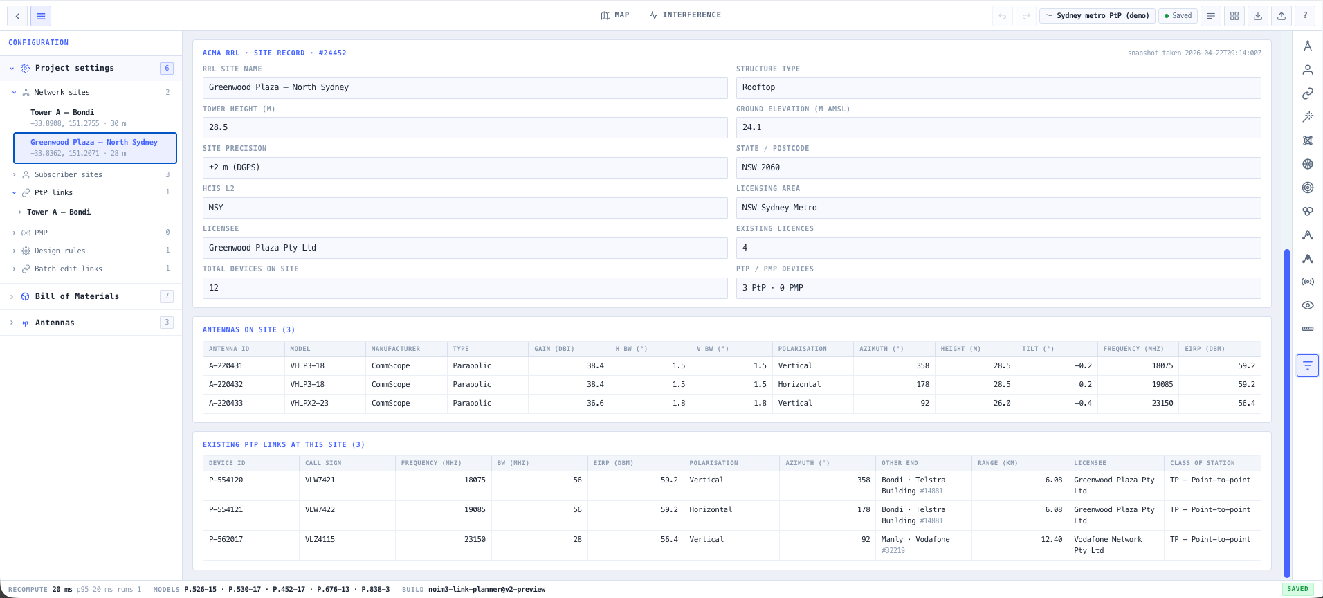
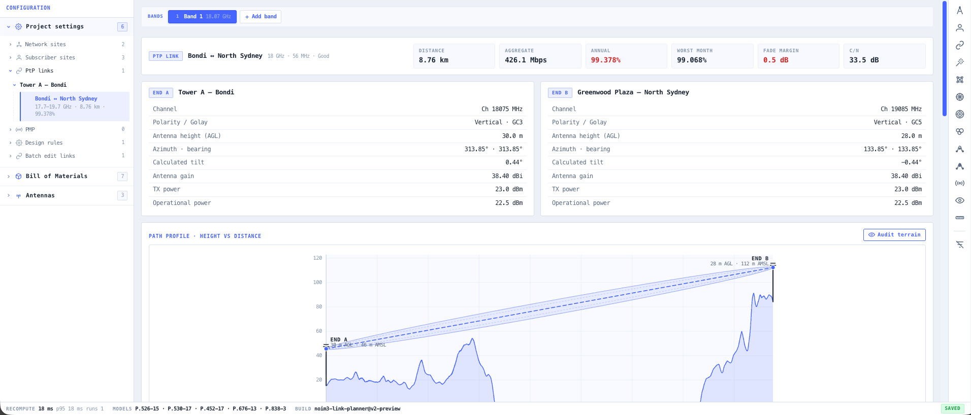
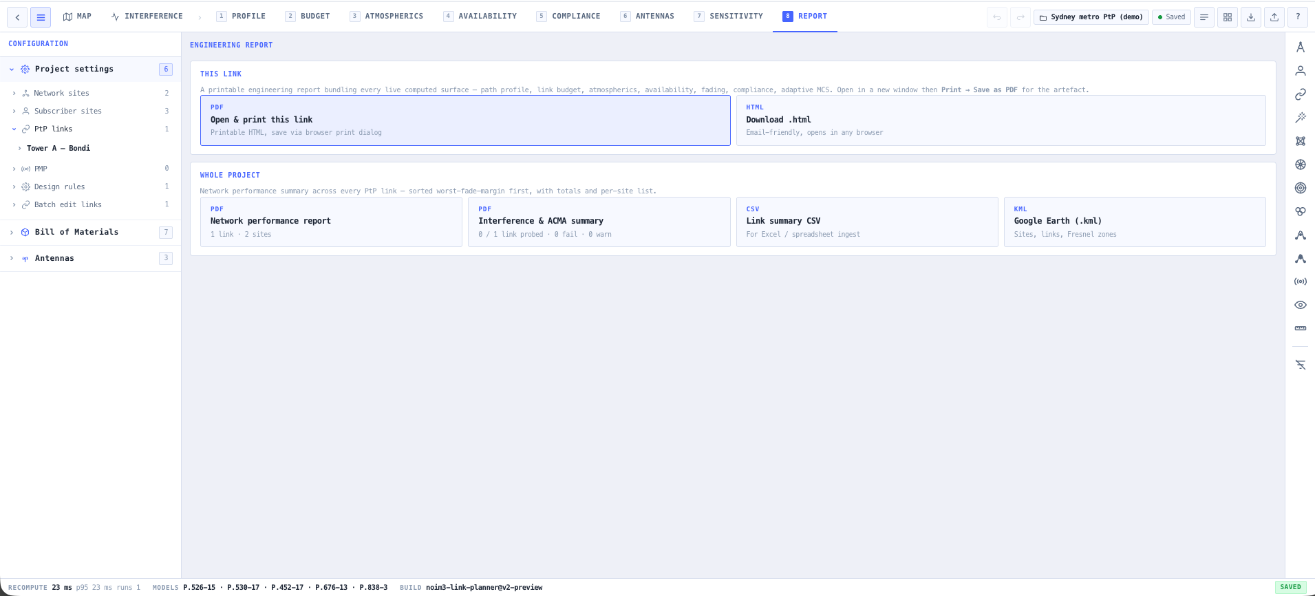
The noIM₃ Point to Point Link Planner is a full ITU anchored RF planning workstation that runs entirely in your browser. It implements ITU P.526 for diffraction, P.530 for line of sight propagation including rain and multipath, P.676 for atmospheric gas absorption, P.838 for rain attenuation coefficients, P.840 for cloud and fog attenuation, and P.2108 for clutter loss. Every number on screen is tied back to the input that produced it, so a link budget is not a black box but an auditable engineering artefact.

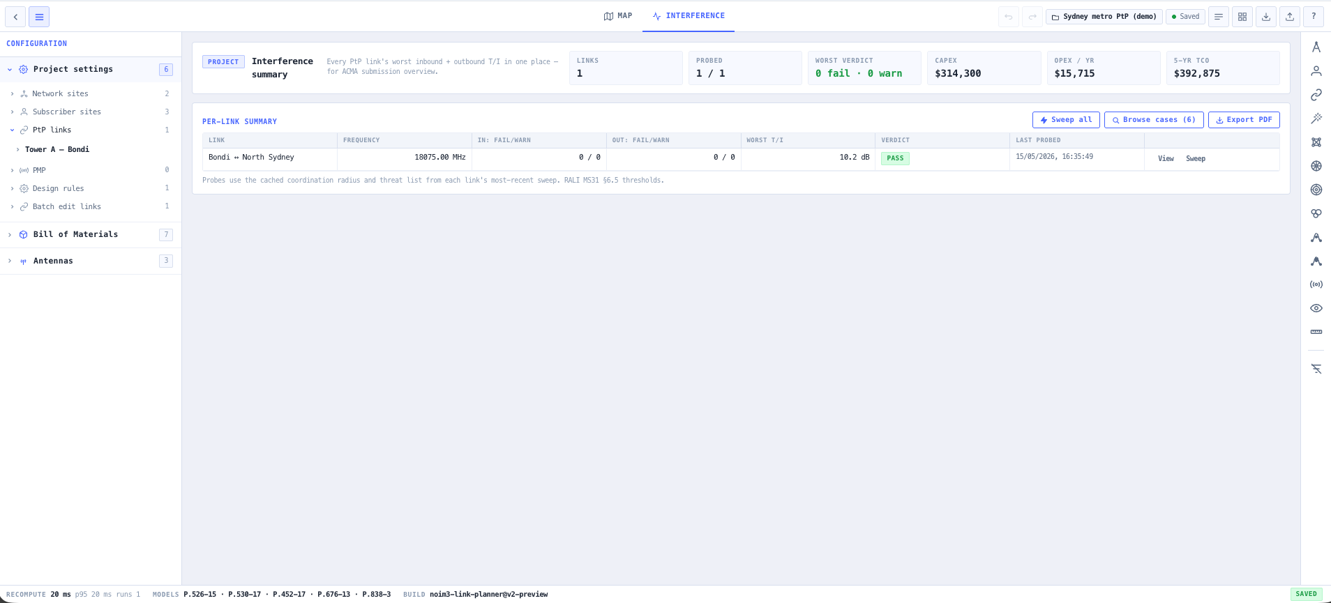
Path profiles are sampled from the Mapbox global Terrain RGB DEM with configurable sampling density and earth curvature treatment, then evaluated against Fresnel zone clearance and ITU diffraction loss. Antenna patterns are modelled with full elevation and azimuth response so that mechanical tilt, twist, and sway are accounted for in the budget. Rain and gas attenuation are conditioned on the local climate using the ITU rain rate maps and BOM data where Australian sites are involved. The result is a link plan that is defensible to a regulator, a customer, or your future self when the network is in service and a fade event needs investigation.

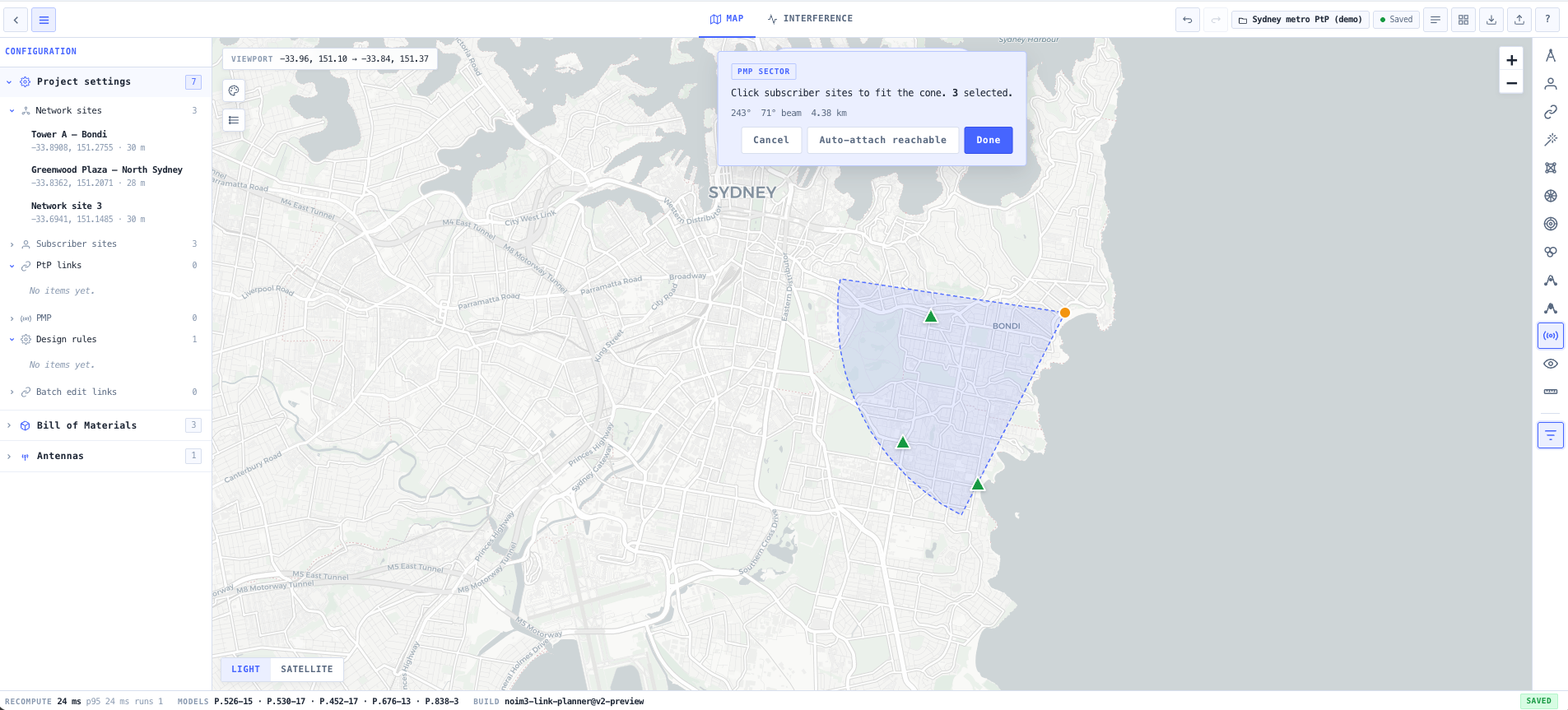
The same workstation plans point to multipoint access as well as point to point backhaul. You draw a sector from a base station over its subscribers, and every base to subscriber leg becomes a real link analysed through the identical engine, so per subscriber clearance, receive level, fade margin, availability, and modulation come from the actual terrain rather than a nominal range circle. Each sector carries its own editable radio configuration of frequency, channel width, polarisation, transmit power, and antenna gain, and changing any of them re-runs the affected legs. The sector is then sized for aggregate downlink throughput using an airtime fair model anchored to each subscriber real net rate, and a co-channel carrier to interference figure is reported for subscribers served by co-located sectors that share a channel, so you can stagger frequencies for clean reuse.

Capabilities

ITU anchored propagation engine

P.526 for diffraction, P.530 for line of sight including rain and multipath, P.676 for atmospheric gases, P.838 for rain attenuation, P.840 for cloud and fog, P.2108 for clutter. Every model is implemented to the latest published recommendation revision.

Terrain accurate path profile

Mapbox global Terrain RGB DEM sampling with configurable density. Earth curvature, k factor, and refractivity are treated explicitly. Fresnel zone clearance is computed at every sample point and surfaced as a clearance ratio along the path.

Full link budget with provenance

Every input that drives a budget value is annotated with its source. Hover any number on the budget and you see exactly which model, which input, and which standard produced it. The result is an audit grade engineering record rather than a black box.

Rain, gas, cloud, and multipath

Rain attenuation per P.530 and P.838 with regional rain rate input or ITU climate maps. Atmospheric gas absorption per P.676. Cloud and fog per P.840. Multipath dispersive fade margin per P.530 with diversity treatment.

Diversity and adaptive modulation

Space, frequency, and angle diversity are modelled explicitly with effective improvement factors. Adaptive modulation availability is computed from the receiver SNR threshold curve and the path fade distribution, not assumed at a single operating point.

Antenna pattern modelling

Full azimuth and elevation antenna patterns are applied at each end. Cross polarisation discrimination, mechanical alignment tolerance, and tower sway are treated as inputs to the budget rather than rules of thumb.

Frequency assignment and coordination

Channel plan generation, G.82x channel allocation rules, ACMA RRL coordination candidate generation, corridor snap, and exclusion zone enforcement built into the planning surface so a candidate plan is also a coordinated plan.

Point to multipoint sectors with real per subscriber budgets

Draw a sector from a base station over its subscribers, and every base to subscriber leg is analysed through the same engine as a point to point link. Per subscriber range, receive level, fade margin, predicted availability, and usable modulation come from the actual terrain profile, and any leg that cannot close at maximum mast height is reported rather than quietly assumed to work.

Sector capacity and co-channel reuse

Each sector carries an editable radio configuration of frequency, channel width, polarisation, transmit power, and antenna gain that re-runs the affected legs when changed. The sector is sized for aggregate downlink throughput using an airtime fair planning estimate anchored to each subscriber real net rate, and a co-channel carrier to interference figure based on the ITU R F.1336 sector pattern is reported for subscribers served by co-located sectors on the same channel, so frequencies can be staggered for clean reuse.

Tabular engineering and sensitivity dashboards

A dense tabular view exposes every parameter for fast bulk editing. Sensitivity dashboards show how the link budget responds to changes in antenna size, transmit power, frequency, rain rate, and path length so margin choices are informed rather than guessed.

Reports, KML, and installer drawings

One click export of long form engineering reports, installer drawings, site network KML, and signed PDFs. Output is structured for ACMA licence applications, customer engineering submissions, and field installation packs.

Project tree and collaboration

Multi link projects are organised in a tree so a network of dozens of hops is navigable rather than a flat list. Project state is persistable, and ITU vector regression diffs surface model behaviour changes between releases.

Standards & methodology

  • ITU P.526. Propagation by diffraction
  • ITU P.530. Propagation data and methods for terrestrial line of sight systems
  • ITU P.676. Attenuation by atmospheric gases
  • ITU P.838. Specific attenuation model for rain
  • ITU P.840. Attenuation due to clouds and fog
  • ITU P.2108. Prediction of clutter loss
  • ITU P.837. Characteristics of precipitation for propagation modelling
  • ITU G.82x. Microwave channel arrangements
  • ACMA RRL coordination data integration for Australian licensing workflows

When to use this tool

  • Designing a new microwave or millimetre wave point to point link from a site survey
  • Validating an existing link against ITU P.530 with current rain rate and atmospheric data
  • Producing engineering documentation for an ACMA microwave licence application
  • Coordinating a candidate channel against existing RRL incumbents along the path
  • Generating installer drawings and site network KML for a multi link rollout
  • Comparing antenna size, frequency, and diversity options against availability targets
  • Diagnosing a working link that is missing its availability target during rain events
  • Producing customer ready engineering reports for a backhaul or transport network
  • Planning resilient backhaul for cellular, mining, utility, and broadcast operators
  • Validating vendor proposed link designs before purchase or rollout
  • Supporting fixed wireless access network expansion with traceable engineering output
  • Planning a point to multipoint sector and checking which subscribers actually close against the terrain before deployment
  • Sizing a point to multipoint sector for downlink capacity and staggering frequencies across sectors for clean co-channel reuse
  • Producing audit grade link budgets for regulatory or compliance review

Is this the right tool for you?

Reach for the Point to Point Link Planner in any of the following situations.

  • You are designing a new microwave or millimetre wave backhaul link from a site survey and need a defensible engineering plan that holds up to regulatory and customer scrutiny.
  • You are operating a backhaul network and a link is failing its availability target during heavy rain, and you need to confirm whether the fade margin design is correct or the antenna size needs to grow.
  • You are preparing an ACMA microwave licence application and need a full link budget, path profile, and coordination check ready for submission with full traceability.
  • You are coordinating a new channel along a corridor that already has incumbents and need ACMA RRL aware candidate generation rather than manually scrubbing the public dataset.
  • You are rolling out a multi hop transport network for a mining, pastoral, utility, or broadcast operator and need installer drawings, site KML, and a single project file that ties them all together.
  • You are evaluating antenna size, transmit power, frequency, and diversity options against an availability target and want to see exactly how each lever changes the budget.
  • You are validating a link plan submitted by a vendor or contractor and want an independent ITU compliant second opinion before you sign off the purchase order.
  • You are responsible for fixed wireless access network expansion and need link plans that scale across dozens of hops with provenance for every input.
  • You are planning a point to multipoint sector from a tower over a cluster of subscriber premises and need to know which subscribers will close, what each will receive, and how much downlink capacity the sector delivers, rather than relying on a nominal coverage radius.
  • You need to produce a customer ready engineering report including path profile, Fresnel clearance, link budget, rain attenuation, and predicted availability without rebuilding the deliverable from a spreadsheet.
  • You are planning a temporary or event link and need a fast plan that still respects ITU diffraction, gas, and rain models rather than a back of envelope estimate.
  • You are planning resilient links across the Australian rain regions and need rain rate input that reflects the actual climate at the path rather than a global default.
  • You are responsible for cellular or 5G backhaul and need link budgets with adaptive modulation availability properly modelled rather than assumed at a single operating point.
  • You are training new RF engineers and want a planning surface that exposes every assumption and every model so the team learns where the numbers actually come from.
  • You are auditing an inherited network and need to reproduce historical link budgets with documented input provenance to confirm the original design assumptions.
  • You need a coordinated channel plan across a large network and want frequency assignment, G.82x allocation, and corridor snap built into the planning workflow.
  • You are a consulting engineer producing tender ready link plans for clients and need exportable PDFs, KML, and signed reports rather than internal screenshots.

Frequently asked questions

Which ITU recommendations does the planner implement?

P.526 for diffraction, P.530 for terrestrial line of sight including rain and multipath, P.676 for atmospheric gas absorption, P.838 for rain attenuation coefficients, P.840 for cloud and fog, P.2108 for clutter loss, and P.837 for rain rate climatology. Each is implemented to the latest published revision and the version used is annotated on the output for provenance.

Where does terrain data come from?

Path profiles are sampled from the Mapbox global Terrain RGB DEM. Sampling density is configurable so you can trade detail against compute time, and earth curvature with a configurable k factor is applied explicitly. Fresnel zone clearance is computed at every sample point.

What does provenance mean on the output?

Every number on the link budget is annotated with the input and the model that produced it. Hover any value and you see the standard, the model revision, and the input parameters that drove it. The point is to make the budget an auditable engineering artefact rather than a black box, especially for regulatory or compliance review.

Does the planner cover ACMA coordination?

Yes. ACMA RRL data is integrated for coordination candidate generation along corridors, with corridor snap, exclusion zones, and G.82x channel allocation built into the planning surface. The coordinated plan and the engineered plan are the same artefact, not two separate workflows.

How is rain attenuation handled?

Rain attenuation is computed per ITU P.530 using P.838 rain rate to attenuation coefficients. You can input a measured or specified rain rate directly, or use the ITU P.837 rain rate climatology for the path location. Output includes the predicted outage and the contribution of rain to total annual unavailability.

Can I model adaptive modulation?

Yes. Adaptive modulation availability is computed across the modulation order set using the receiver SNR threshold curve and the path fade distribution. Output is a per modulation availability table rather than a single point assumption, which matches how modern microwave radios actually behave in service.

What about diversity?

Space, frequency, and angle diversity are modelled with effective improvement factors per P.530. The improvement is applied to multipath fade margin rather than assumed across the whole budget, and the configuration is captured in the provenance trail.

Does it plan point to multipoint as well as point to point?

Yes. You draw a sector from a base station over its subscribers, and every base to subscriber leg is analysed through the same engine as a point to point link, so per subscriber clearance, receive level, fade margin, availability, and modulation come from the real terrain. Each sector has an editable radio configuration of frequency, channel width, polarisation, transmit power, and antenna gain that re-runs the affected legs when changed. The sector is sized for aggregate downlink throughput with an airtime fair estimate anchored to each subscriber net rate, and a co-channel carrier to interference figure is reported for subscribers served by co-located sectors on the same channel so frequencies can be staggered for reuse.

What outputs are available for licensing and field work?

Long form engineering reports as PDF, installer drawings, site network KML, signed exports for compliance review, and a regression diff against ITU vector test cases. Output is structured for ACMA licence applications, customer engineering submissions, and field installation packs.