RF Utilities

N-Way Power Divider Calculator

Power divider and combiner budgeting for RF systems integration. Split loss across N ports, excess versus total insertion loss, transmitter combining and isolation-load dissipation, tree versus single-stage architectures, and power handling headroom.

Free forever on a Standard account. No credit card.

Overview

A power divider looks like the simplest passive in the rack, and it is the one most often budgeted wrong. Splitting a signal equally among N ports costs 10 log N in dB, about 3 dB for a 2-way, 6 dB for a 4-way, 9 dB for an 8-way, and 12 dB for a 16-way. That is not a loss the divider dissipates, it is the division of the input among the ports, and it is the number people forget when a link comes up short. On top of it sits a real excess loss, and the two are quoted together on datasheets in two incompatible ways that are the classic source of error.

The noIM₃ N-Way Power Divider Calculator is the power-budget utility for that work, written for a systems integrator rather than a circuit designer. It does not synthesise Wilkinson resistors or quarter-wave transformers. It answers the question that matters on site: what power reaches each port, what is lost, and what is dumped. Divide mode splits one input equally or by arbitrary weights and reports the split loss, the excess loss, the total insertion loss, and the per-port power in dBm and watts, with a first-class switch for whether the datasheet quotes excess or total insertion loss because getting it backwards is a 3 dB error on a 2-way and a 12 dB error on a 16-way.

Combine mode runs the divider backwards and forces the distinction that trips people up. Separate carriers do not add in power the way intuition suggests: each carrier reaching the common port is down by the full split, and the surplus is burned in the internal isolation loads, so paralleling two 100 W transmitters gives about 100 W at the antenna and dumps about 100 W in a resistor. A coherent signal recombined in phase does add fully at plus 10 log N. Tree mode compares a cascaded architecture against one single equivalent N-way divider so the loss penalty of the extra stages is explicit, and Power mode checks input, per-port, and isolation-load headroom with a planning-grade derating.

Capabilities

Per-port power from an N-way split

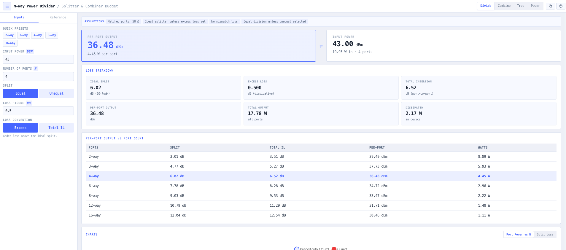
Enter the input power and the number of ports and read the per-port output in dBm and watts, with the ideal split loss of 10 log N, the excess dissipative loss, and the total port-to-port insertion loss reported separately so the division of power and the real loss are never conflated.

Excess versus total insertion loss, made explicit

Divider datasheets quote loss two ways, and reading one as the other is the classic mistake. Excess loss is the added loss above the ideal split; total insertion loss already includes the split. The convention is a switch rather than an assumption, and the tool warns when a quoted total is below the ideal split for its port count, which is physically impossible.

Unequal, tapered splits

Model a tapered divider by entering a linear weight per port. The tool normalises the weights to power fractions, applies the excess loss, and reports each port by coupling, share, and output, with the amplitude balance across the ports as the single figure a distribution design has to hold.

Combining transmitters, done honestly

Separate carriers each drop the full 10 log N split and the surplus is burned in the isolation loads, so combining N equal transmitters yields about one transmitter of output while a fraction of one minus one over N is dumped. The tool reports the output, the per-carrier level, the dumped power and its percentage, and the combining gain, so the resistor dissipation is designed for rather than discovered.

Coherent combining and isolation leakage

For one signal split, amplified, and recombined in phase, the paths add fully at plus 10 log N with nothing dumped. The tool also turns the port isolation figure into the reverse-coupled power at a neighbouring transmitter port, the number that feeds an inter-transmitter interference or intermodulation check.

Tree versus single-stage architecture

Reaching many ports can be done with one large divider or a cascaded tree with inter-stage cable. The split loss is identical either way, so the tool isolates the real trade: the tree pays extra for its stage excess losses and cabling, while the single stage wins on loss and the tree wins on physical distribution. Both totals and the penalty are reported.

Power handling and fault reflection

Check the input-port, per-port, and isolation-load power headroom against component ratings, apply a planning-grade temperature derating, and estimate the power reflected back into the loads under an open or shorted output fault. Overloads are flagged so an undersized combiner load is visible before it fails in the field.

Browser only computation

Runs entirely in your browser. No powers, port counts, or network configurations are submitted to a server. Useful for commercially confidential work, classified projects, or any environment where information security policy prohibits sending engineering data to third party services.

Standards & methodology

  • Ideal split loss defined as 10 x log10(N) dB, the division of the input among the ports
  • Total insertion loss defined as the ideal split plus the excess dissipative loss
  • Combining of separate carriers as a power-basis sum with a dumped fraction of 1 - 1/N
  • Coherent combining as a voltage-basis sum reaching plus 10 x log10(N)
  • Power headroom as the rating less the applied power, with a planning-grade linear derating

When to use this tool

  • Sizing the per-port power reaching each antenna from a splitter in a distributed antenna system
  • Reading a divider datasheet correctly by separating the excess loss from the total insertion loss
  • Checking what a 4-way or 8-way split costs a signal before it reaches the far port
  • Modelling a tapered, unequal split and holding the amplitude balance across the ports
  • Showing a client why combining two 100 W transmitters does not give 200 W at the antenna
  • Sizing the isolation-load dissipation when combining transmitters onto a shared feeder
  • Turning a combiner isolation figure into the reverse-coupled power at a neighbouring transmitter
  • Deciding between a single N-way divider and a cascaded tree for a distribution network
  • Comparing the loss penalty of a two-tier tree against a single equivalent divider
  • Checking the input, per-port, and isolation-load power headroom against component ratings
  • Estimating the power reflected back into a combiner load under an open or shorted output fault
  • Sanity checking a quoted divider insertion loss against the ideal split for its port count

Is this the right tool for you?

Reach for the N-Way Power Divider Calculator in any of the following situations.

  • You are feeding four antennas from one source in a distributed antenna system and need the power at each antenna port after the split and the divider loss.
  • You are reading a divider datasheet that quotes 6.5 dB on a 4-way and need to know whether that is the excess loss or the total insertion loss before you trust the number.
  • You are designing a tapered split that has to hold a 3 dB amplitude balance across the ports and want the per-port coupling and output for a set of weights.
  • You are combining two 100 W transmitters onto one feeder and need to explain to a client why the antenna sees about 100 W and where the other 100 W goes.
  • You are sizing the internal load of a transmitter combiner and need the dumped power under normal operation before you trust its rating.
  • You have a combiner with 25 dB of port isolation and need the reverse-coupled power landing on the neighbouring transmitter for an intermodulation check.
  • You are choosing between a single 8-way divider and a three-tier tree of 2-way splitters and need the loss penalty of the tree over the single stage.
  • You are planning a distribution network across a large site and need to weigh the extra loss of a cascade against the cabling a single central divider would demand.
  • You are checking whether a divider rated for 100 W has enough headroom for a 20 W drive at elevated temperature after derating.
  • You need the power reflected back into a combiner load if an output port is left open or shorted during commissioning.
  • You are auditing an existing feeder network and want to sanity check the quoted divider losses against the ideal split for each port count.
  • You are operating under a security regime that prohibits sending design data to third party services and need a calculator that runs entirely in your browser.

Frequently asked questions

How much loss does an N-way power divider have?

At least the ideal split loss of 10 log N in dB, which is about 3 dB for a 2-way, 6 dB for a 4-way, 9 dB for an 8-way, and 12 dB for a 16-way. That is not a loss the divider dissipates, it is the division of the input among the ports. A real device adds a small excess dissipative loss on top, typically a few tenths of a dB for a reactive or ferrite divider, so the total port-to-port insertion loss is the split plus the excess. The calculator reports all three separately.

What is the difference between excess loss and insertion loss on a divider datasheet?

Excess loss is the added dissipative loss above the theoretical split, so a 4-way with 0.5 dB excess loss delivers each port at the input less 6 dB less 0.5 dB. Total insertion loss is the whole port-to-port figure with the split already included, so the same device would be quoted as about 6.5 dB total insertion loss. The relationship is total equals split plus excess. Reading one as the other is the classic divider mistake, and the error scales with the port count, 3 dB on a 2-way and 12 dB on a 16-way. The calculator makes the convention an explicit switch and warns when a quoted total is below the ideal split.

If I combine two 100 W transmitters, do I get 200 W?

Not through a broadband hybrid or Wilkinson combiner. For two separate carriers that device is a divider run backwards, so each transmitter reaches the common port down by the 3 dB split, giving about 50 W each, for a total of about 100 W at the antenna. The other 100 W is burned in the internal isolation load. In general, combining N equal separate carriers this way yields about one carrier of output power while a fraction of one minus one over N of the total input is dumped in the loads. There are two ways to avoid that penalty: combine coherently, a single signal split, amplified, and recombined in phase, which reaches the full N-times combination; or, when the transmitters are on different frequencies, use a frequency-selective diplexer, multiplexer, or cavity combiner, which is a different device that combines the separate frequencies with low loss rather than dumping the surplus. The calculator models the hybrid and coherent cases; the frequency-selective case is a distinct topology.

When does coherent combining apply?

When the inputs are correlated: one signal split into several paths, amplified separately, and recombined in phase, as in a balanced or coherent power-combining amplifier. In that case the paths add on a voltage basis and the output is the per-port power plus 10 log N, with nothing dumped for equal amplitudes. Two 50 W amplifiers driven coherently combine to about 100 W. If the inputs are different carriers, the coherent result does not apply and the separate-carrier arithmetic governs. The distinction is the whole point of the Combine mode, so the tool asks rather than assuming.

Is a single N-way divider better than a tree of smaller ones?

On loss, almost always yes, because the ideal split loss is identical either way (10 log of the product of the stage ways equals the sum of the per-stage splits) but the tree carries an extra excess loss at every stage plus the cabling between stages. On physical layout the tree often wins, because it lets you place smaller dividers near clusters of ports instead of running many cables back to one central unit. The Tree mode reports the loss both ways and the penalty, so the decision is made on the real number rather than a rule of thumb.

Does this tool design the divider itself?

No. It is a distribution-network power budget for systems integration, not a circuit-design tool. It does not synthesise Wilkinson resistor values, quarter-wave transformer impedances, or microstrip geometry, and it does not work in S-parameters. It answers the integration questions: what power reaches each port, how to read the datasheet, how much is dumped when combining, which architecture loses less, and whether the power handling has headroom. For the internal design of a divider you would use an RF circuit simulator.

Where do the divider technology figures come from?

They are indicative ranges for each technology class (reactive and Wilkinson, ferrite hybrid, and resistive), offered so a quoted figure can be placed against the technology it implies. They are not a specification, they are not drawn from any particular datasheet, and they are not a substitute for the datasheet of the part you are actually specifying. Real parts vary widely inside each class and vendors quote loss and isolation over different bands. Use the classes for orientation and the datasheet for decisions.

Does any data leave my browser?

No. The calculator runs entirely in your browser. No powers, port counts, or network configurations are submitted to a server. Useful for commercially confidential work, classified projects, or environments where information security policy prohibits sending engineering data to third party services.