RF Utilities

Adjacent Channel Rejection Calculator

ACS, ACLR, and ACIR calculator for RF systems integration. Compute the margin a receiver keeps against an adjacent-channel interferer, the leakage a transmitter puts on its neighbour, the combined adjacent-channel isolation, and whether two systems on neighbouring channels coexist.

Free forever on a Standard account. No credit card.

Overview

Put two systems on neighbouring channels and interference leaks between them two ways, and both matter. The transmitter is not perfectly clean, so some of its power falls in the adjacent channel, set by its adjacent-channel leakage ratio, ACLR. The receiver is not perfectly selective, so a strong signal in the adjacent channel is not fully rejected, set by its adjacent-channel selectivity, ACS, also called adjacent-channel rejection, ACR. A frequency plan that looks at only one of the two can be wrong by a wide margin, because the two add and the worse one usually dominates.

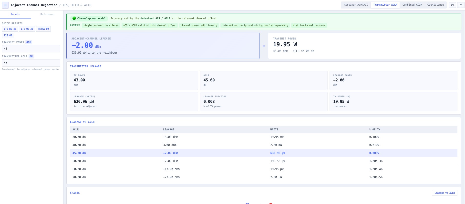
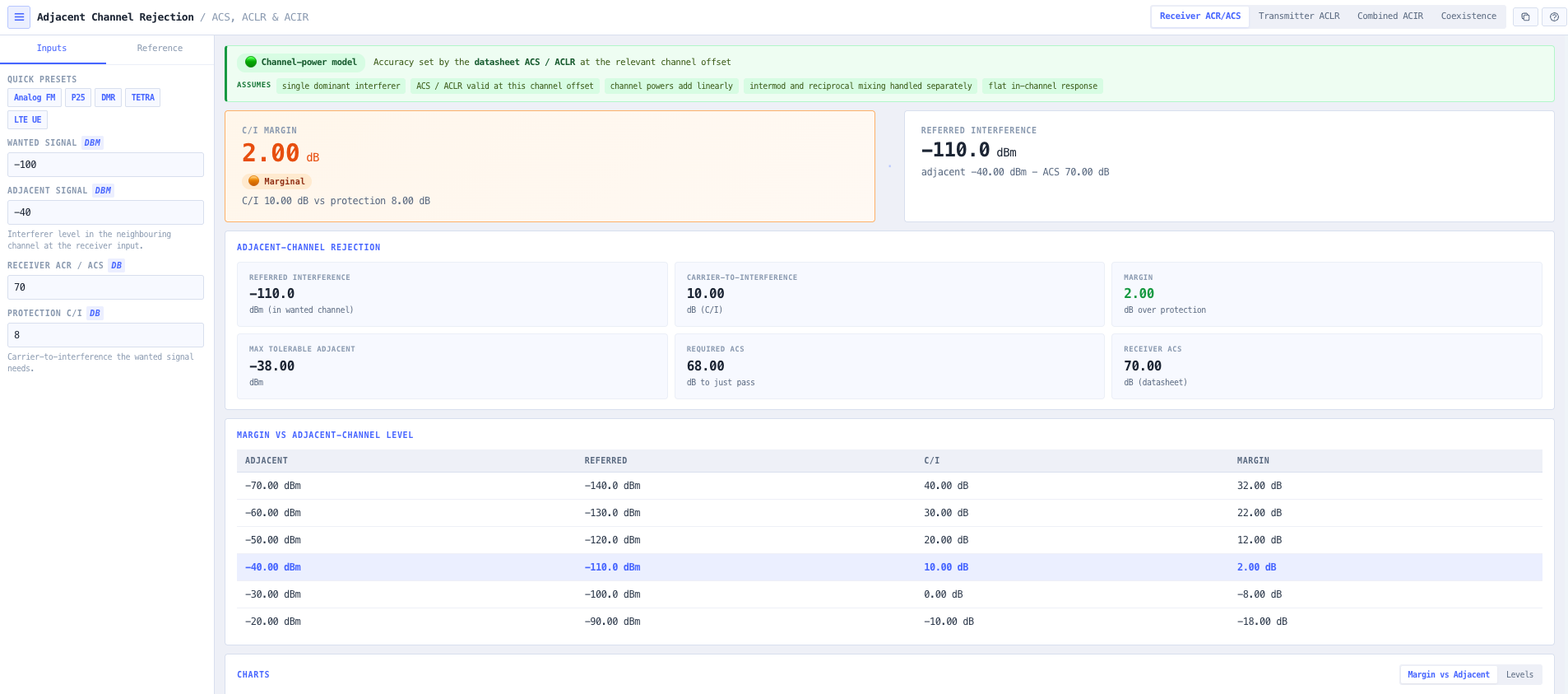
The noIM₃ Adjacent Channel Rejection Calculator is the interference utility for that work, written for a systems integrator rather than a filter designer. The ACLR and ACS are datasheet and standards figures, not synthesised, and the output is framed as the numbers that decide a frequency plan. The Receiver ACR/ACS mode refers the adjacent interferer into the wanted channel as the adjacent level less the ACS, computes the carrier-to-interference ratio, and reports the margin over the protection ratio, the highest tolerable adjacent level, and the ACS a receiver would need to just pass. The Transmitter ACLR mode reports the power a transmitter leaks into the adjacent channel in dBm, watts, and as a fraction of the transmit power.

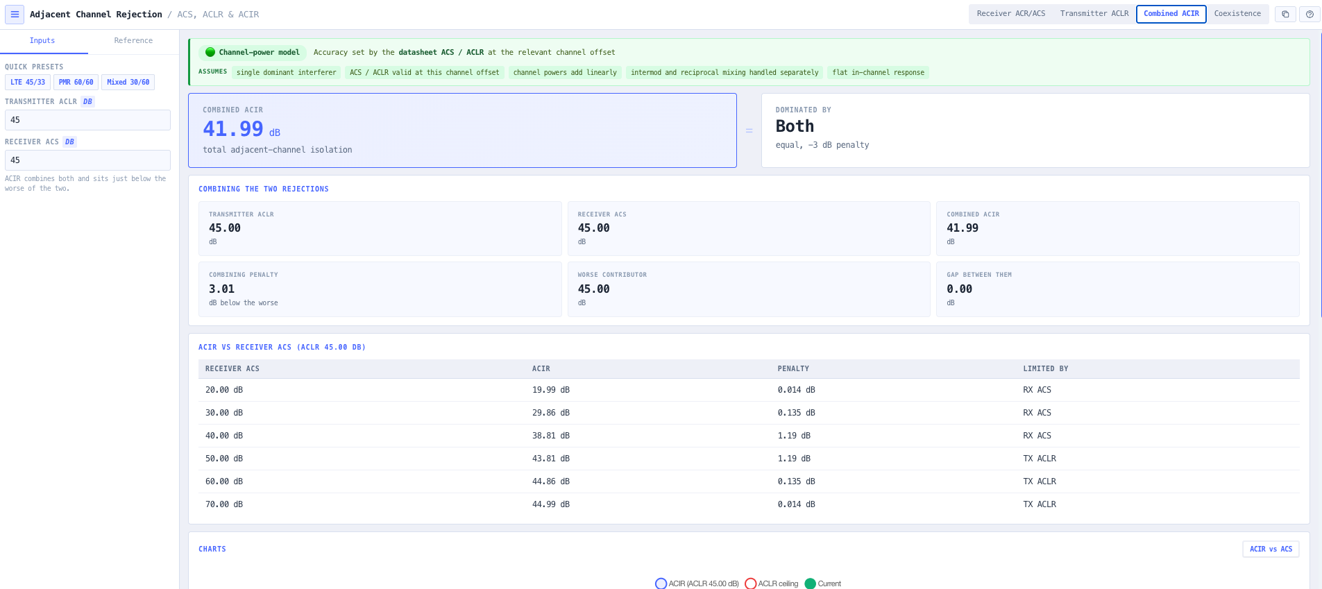
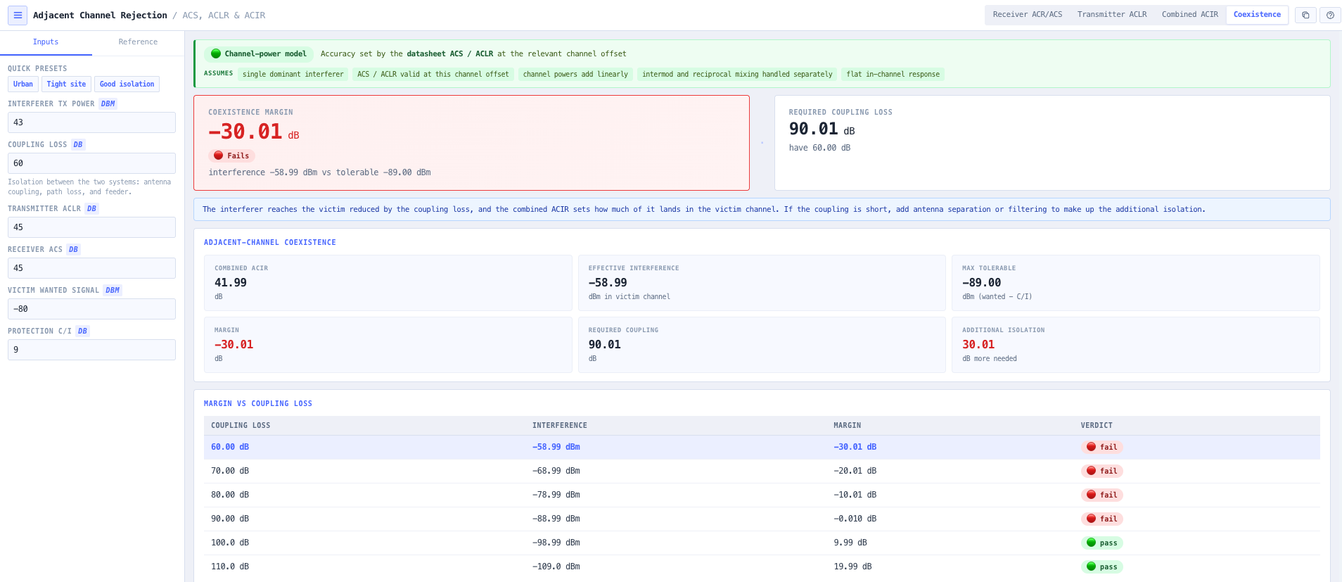
The Combined ACIR mode is the systems-integration heart. The transmitter leakage and the receiver selectivity add on a power basis, so the total adjacent-channel isolation is ACIR = −10·log₁₀(10^(−ACLR/10) + 10^(−ACS/10)), which sits just below whichever contributor is worse. The Coexistence mode turns that into a deployment answer: for an interferer and a victim on adjacent channels, the effective interference is the transmit power less the coupling loss and the ACIR, and the tool reports the margin, the coupling loss the pair needs, and the extra isolation to make up with separation or filtering.

Capabilities

Receiver adjacent-channel margin

Enter the wanted signal, the adjacent interferer, the receiver ACS, and the protection ratio, and the tool refers the interferer into the wanted channel, computes the carrier-to-interference ratio, and reports the margin, colour coded pass or fail, with the highest tolerable adjacent level and the ACS needed to just pass.

Transmitter adjacent-channel leakage

The power a transmitter leaks into the adjacent channel is the transmit power less the ACLR. The tool reports it in dBm, in watts, and as a fraction of the transmit power, so the absolute interference a transmitter puts on its neighbour is explicit.

The combined ACIR

The transmitter leakage and the receiver selectivity add: ACIR = −10·log₁₀(10^(−ACLR/10) + 10^(−ACS/10)). The result sits just below whichever contributor is worse, and the tool identifies the dominant mechanism and the combining penalty, so effort goes where it helps.

Why the worse one wins

Two equal contributors give a 3 dB penalty, so 60 dB ACLR with 60 dB ACS gives about 57 dB. When one is much worse the combined figure is essentially the worse one, so a 45 dB ACLR with a 75 dB ACS gives about 45 dB. Improving the already-better one buys almost nothing, and the tool makes that visible.

Coexistence of two systems

For an interferer and a victim on adjacent channels, the effective interference is the transmit power less the coupling loss and the ACIR. The tool compares it against what the victim tolerates and reports the margin with a pass or fail, plus the coupling loss the pair needs and the additional isolation to make up if the coupling is short.

From a frequency conflict to a physical requirement

Coexistence mode turns an adjacent-channel conflict into an isolation requirement in dB, which becomes an antenna separation or a filter. It is the bridge between the frequency plan and the physical site, and it works backwards from the required margin to the isolation that delivers it.

A channel-power model, honestly bounded

The model treats the interference as channel powers that add. Intermodulation and reciprocal mixing are separate mechanisms, handled by the spurious-free dynamic range and receiver desensitisation tools. A prominent confidence indicator carries the assumptions on every screen.

Browser only computation

Runs entirely in your browser. No signal levels, rejection figures, or site parameters are submitted to a server. Useful for commercially confidential work, classified projects, or any environment where information security policy prohibits sending engineering data to third party services.

Standards & methodology

  • Receiver adjacent-channel selectivity (ACS / ACR) referring the adjacent signal into the wanted channel by the ACS
  • Transmitter adjacent-channel leakage ratio (ACLR / ACPR) as the in-channel to adjacent-channel power ratio
  • Combined ACIR = −10·log₁₀(10^(−ACLR/10) + 10^(−ACS/10)), per 3GPP
  • Carrier-to-interference protection ratio as the required C/I for the wanted signal
  • Channel-power model: single dominant interferer, powers add, intermod and reciprocal mixing handled separately

When to use this tool

  • Computing the margin a wanted signal keeps against an adjacent-channel interferer
  • Finding the highest adjacent-channel level a receiver tolerates
  • Working out the receiver ACS a frequency plan demands
  • Computing the power a transmitter leaks into the adjacent channel
  • Combining a transmitter ACLR and a receiver ACS into the total adjacent-channel isolation
  • Finding which of the transmitter and the receiver limits the adjacent-channel isolation
  • Checking whether two systems on adjacent channels can share a site
  • Sizing the coupling loss or antenna separation two adjacent-channel systems need
  • Sizing the extra filtering needed when the coupling loss is short
  • Comparing the adjacent-channel performance of different standards
  • Turning an adjacent-channel frequency conflict into a physical isolation requirement
  • Teaching adjacent-channel rejection, leakage, and the ACIR combination

Is this the right tool for you?

Reach for the Adjacent Channel Rejection Calculator in any of the following situations.

  • You are planning a channel next to an existing system and need the margin the wanted signal keeps against the neighbour at its expected level.
  • You have a receiver with a 65 dB ACS and want the highest adjacent-channel level it tolerates before the wanted signal degrades.
  • You are writing a receiver specification and need the ACS the frequency plan demands for a known adjacent interferer.
  • You have a 20 W transmitter with a 45 dB ACLR and want the absolute power it leaks into the neighbouring channel.
  • You are combining a base station ACLR of 45 dB with a receiver ACS of 33 dB and want the total adjacent-channel isolation.
  • You cannot decide whether to buy a cleaner transmitter or a more selective receiver and want to see which one limits the isolation.
  • You are co-locating two systems on adjacent channels and need the coupling loss they need to coexist.
  • You have a fixed antenna separation and want to know whether two adjacent-channel systems coexist or need filtering.
  • You are comparing an analog FM system against an LTE system for adjacent-channel performance.
  • You are turning an adjacent-channel frequency conflict into an antenna separation or a cavity filter requirement.
  • You are training junior engineers on why both the transmitter and the receiver matter for adjacent-channel interference.
  • You are operating under a security regime that prohibits sending design data to third party services and need a calculator that runs entirely in your browser.

Frequently asked questions

What is the difference between ACS, ACR, ACLR, and ACIR?

ACS (adjacent-channel selectivity) and ACR (adjacent-channel rejection) are the same receiver figure: how much stronger an adjacent-channel signal can be than the wanted before it degrades it. ACLR (adjacent-channel leakage ratio, sometimes ACPR) is a transmitter figure: the ratio of the in-channel power to the power the transmitter leaks into the adjacent channel. ACIR (adjacent-channel interference ratio) combines the two into the total isolation between an interfering transmitter and a victim receiver on the adjacent channel. All four are ratios in dB where higher is better.

How do I calculate the combined ACIR?

Add the two leakage paths on a power basis and invert. ACIR = −10·log₁₀(10^(−ACLR/10) + 10^(−ACS/10)). For example a 45 dB ACLR and a 33 dB ACS give −10·log₁₀(10^(−4.5) + 10^(−3.3)) ≈ 32.7 dB, dominated by the receiver ACS. Two equal contributors give a 3 dB penalty, so 60 dB and 60 dB combine to about 57 dB. The calculator does this and reports which mechanism dominates.

Why does the worse of ACLR and ACS dominate?

Because the two are leakage paths that add, and a sum is dominated by its largest term. If the transmitter leaks a fraction 10^(−ACLR/10) of its power into the adjacent channel and the receiver passes a fraction 10^(−ACS/10) of an adjacent signal, the total interference fraction is the sum of the two. When one fraction is much larger than the other, the sum is essentially the larger one, so the worse (smaller-dB) of ACLR and ACS sets the combined ACIR. Improving the already-better one changes almost nothing, which is the key planning insight.

How do I know if two systems on adjacent channels will interfere?

Work out the effective interference at the victim and compare it against what the victim tolerates. The interferer power reaches the victim reduced by the coupling loss between them, and the combined ACIR sets how much lands in the victim channel, so the effective interference is the transmit power less the coupling loss less the ACIR. The victim tolerates interference up to its wanted signal less the protection ratio. If the effective interference is below that, they coexist; if not, they interfere. The Coexistence mode computes the margin and the coupling loss the pair needs.

What coupling loss or antenna separation do two adjacent-channel systems need?

Enough that the effective interference falls below what the victim tolerates. The required coupling loss is the transmit power less the ACIR less the tolerable interference level. If the coupling you have is short of that, the difference is the additional isolation you must add, with antenna separation or a filter. The Coexistence mode reports both the required coupling loss and the additional isolation, so an adjacent-channel conflict becomes a physical requirement in dB that you can deliver with a mast layout or a cavity.

Does this tool handle intermodulation or blocking?

No, those are separate mechanisms. This tool is a channel-power model for adjacent-channel interference: the transmitter leaks power into the neighbour and the receiver imperfectly rejects it. Intermodulation, where two or more signals mix in a nonlinearity to land a product on the wanted channel, is covered by the Spurious-Free Dynamic Range and Intermodulation tools. Blocking and reciprocal mixing, where a strong nearby carrier desensitises the receiver, are covered by the Receiver Desensitisation tool. Use this one for the adjacent-channel case and those for the others.

Where do the ACS and ACLR figures come from?

From the equipment datasheet and the relevant standard. The Reference tab lists indicative ranges by standard for orientation: analog FM at 70 to 80 dB ACS, P25, DMR, and TETRA around 60 dB, and LTE and 5G NR with an ACS around 33 dB and a base station ACLR around 45 dB. These are ballpark figures to place a quoted number against the technology it implies. They are not a specification, and the actual figure depends on the exact standard, the equipment class, and the channel offset, so the datasheet governs.

Does any data leave my browser?

No. The calculator runs entirely in your browser. No signal levels, rejection figures, or site parameters are submitted to a server. Useful for commercially confidential work, classified projects, or environments where information security policy prohibits sending engineering data to third party services.