Electrical System Design

DC Power System Designer

Design the telecom DC power plant — -48 V / +24 V / substation 110–125 VDC — from the load schedule up: rectifier plant sizing with N+1 redundancy, IEEE 485 battery reserve, and the DC distribution voltage budget against the ETSI EN 300 132-2 equipment window.

Free forever on a Standard account. No credit card.

Overview

Almost every piece of communications equipment in the world — the BTS, the exchange, the microwave terminal, the transmission node, the repeater — runs on DC, and overwhelmingly on a -48 V DC power plant. That plant is a discipline of its own: a rectifier system that converts mains AC to a tightly regulated DC bus, a battery that carries the load through a mains failure for a defined reserve time, and a DC distribution network whose voltage budget has to keep the equipment inside its operating window even at the end of a discharge. Get the rectifier count wrong and the plant cannot recharge the battery; get the battery sizing wrong and the site drops before the generator starts; get the distribution drop wrong and the equipment browns out at the worst possible moment.

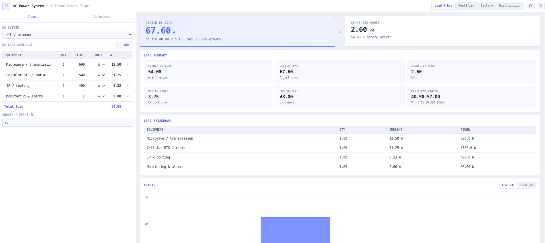
The noIM₃ DC Power System Designer is built for exactly that work, and it is deliberately not the renewable-energy problem the BESS & Solar designer solves. It starts from a DC load schedule on a -48 V, +24 V, or substation 110/125 VDC bus — each line in watts or amps — and resolves the current at the busbar and a design load with a growth margin. From that single load it sizes the rectifier plant, the battery reserve, and the distribution conductors as one linked design: edit the load and every downstream answer follows.

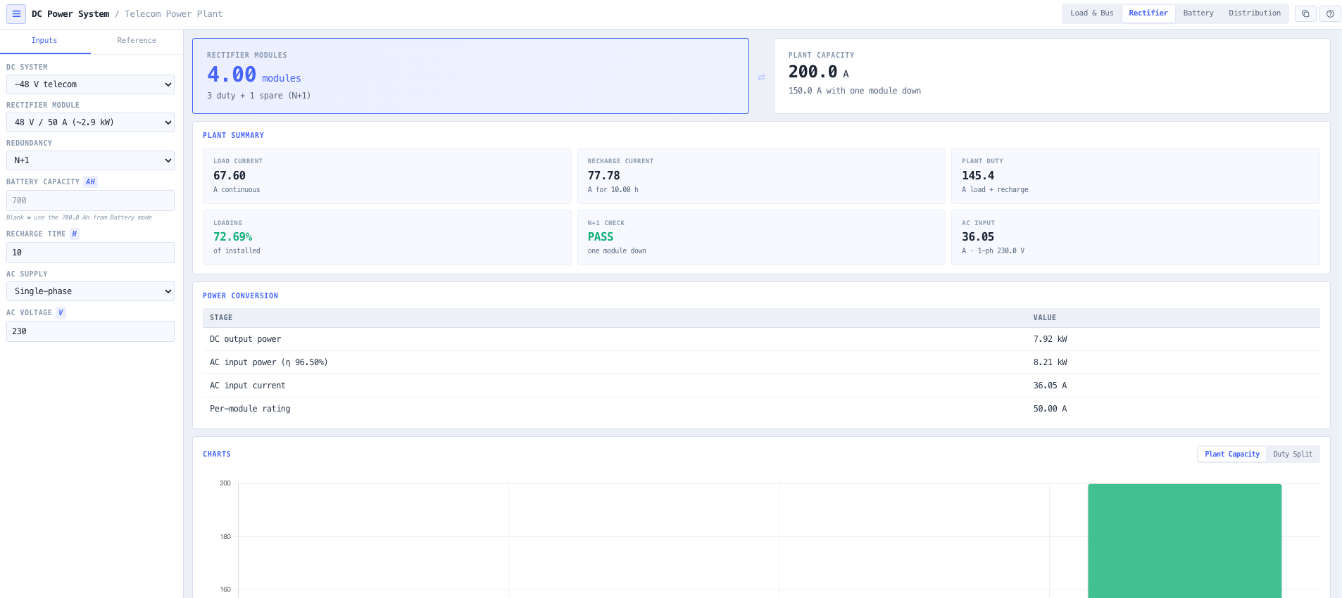
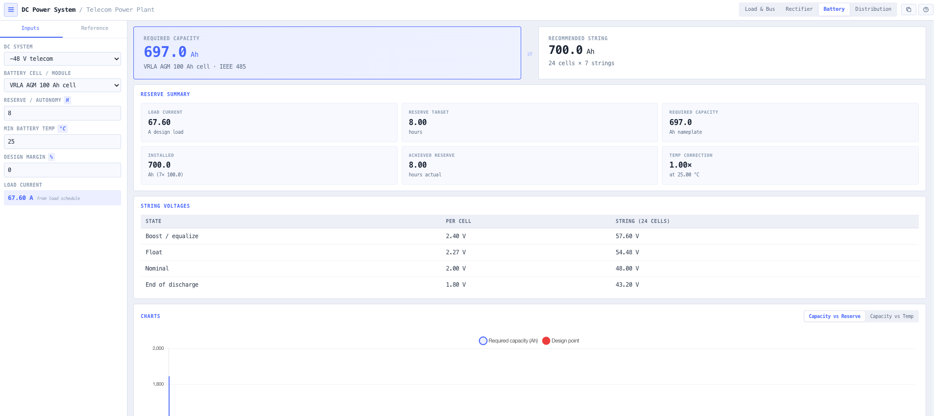
The rectifier mode sizes the modules to carry the load plus the battery recharge current, adds N+1 or N+2 redundancy, runs an n−1 check, and derives the AC input current. The battery mode sizes the reserve by the IEEE 485 (lead-acid) and IEEE 1115 (nickel-cadmium) method — the capacity-rate factor at the reserve duration, a 1.25 end-of-life aging factor, a low-temperature capacity correction, and an optional design margin — and reports the string voltages. The distribution mode sizes the feed and return conductors for the DC voltage budget so the load stays above its window minimum at end-of-discharge, and checks both ends of the window against the boost charge and the discharged voltage. Everything runs in the browser, copies to the clipboard for the design file, and is labelled as planning-grade guidance to confirm against the battery, rectifier and cable datasheets.

Capabilities

One DC load, one linked design

Build the connected load from a schedule of equipment on the chosen DC bus, each line entered in watts or amps with a quantity. The tool resolves the current at the busbar and a design load with a growth margin, and that single load feeds the rectifier, battery and distribution modes so the whole plant stays consistent as you edit.

System voltage and equipment window

Pick the DC system — -48 V telecom (ETSI EN 300 132-2, -40.5 to -57.0 V window), +24 V, or substation 110/125 VDC (IEEE 946) — and the tool carries its nominal voltage and the equipment operating window through every calculation, so the battery end-of-discharge voltage and the boost charge are both checked against the limits the equipment is specified to.

Rectifier plant sizing with N+1 / N+2

Size the rectifier modules to carry the continuous load plus the battery recharge current — the recharge current restoring the bank within a target time with an allowance for charge inefficiency. Add N+1 or N+2 redundancy, and the tool runs an n−1 check (can the plant still carry the duty with one module failed?) and derives the AC input current for single- or three-phase supply.

IEEE 485 / IEEE 1115 battery reserve

Size the battery for the reserve time by the recognised method: required capacity is the load current times the reserve hours, divided by the capacity-rate factor at that discharge duration, multiplied by a 1.25 end-of-life aging factor, a low-temperature capacity correction, and an optional design margin. The tool picks the parallel strings, reports the installed capacity and the reserve actually achieved, and lays out the float, boost, nominal and end-of-discharge string voltages.

Battery chemistry library

Choose VRLA AGM, VRLA gel, flooded lead-acid, nickel-cadmium, or lithium iron phosphate. Each carries representative per-cell float, boost and end-of-discharge voltages, a capacity-rate curve (lead-acid loses a large fraction of capacity at short, high-current durations; lithium holds up far better), and a temperature correction, so the chemistry choice changes the sizing the way it does in practice.

DC distribution voltage budget

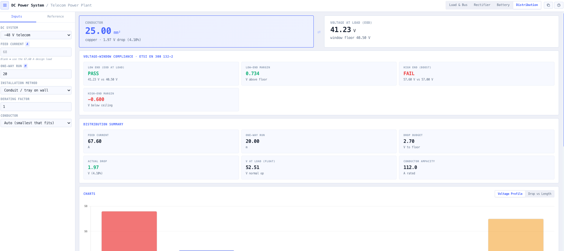
Size the feed and return conductors for the DC voltage budget. The round-trip drop across both conductors is computed at the feed current, and the smallest copper conductor that carries the current and keeps the load above its window minimum at end-of-discharge is selected, with the voltage at the load reported at both float and end-of-discharge.

Voltage-window compliance check

The plant is checked at both ends of the equipment window: the end-of-discharge voltage minus the distribution drop against the window floor (will the equipment brown out at the end of a discharge?), and the boost / equalize charge against the window ceiling (will boost charging over-volt the equipment?). Pass / fail with the margin in volts at each end.

Browser-only, planning-grade, copy to clipboard

Runs entirely in your browser — no load schedule or site data is submitted to a server, which suits commercially confidential and security-restricted communications sites. Every modelled figure is labelled as planning-grade guidance anchored to a published standard, to confirm against the chosen battery, rectifier and cable datasheets. Each mode copies a plain-text summary for the design file.

Standards & methodology

  • ETSI EN 300 132-2 — DC power interface at -48 V and the equipment input voltage window
  • ETSI EN 300 132-3 — power supply up to 400 VDC / +24 V information and communications equipment
  • Telcordia GR-3168 / GR-947 — telecommunications DC power systems and rectifiers
  • IEEE 485 — sizing vented and valve-regulated lead-acid batteries for stationary applications
  • IEEE 1115 — sizing nickel-cadmium batteries for stationary applications
  • IEEE 946 / IEEE 1184 — DC auxiliary power systems for substations and generating stations

When to use this tool

  • Sizing the -48 V rectifier plant and battery for a new BTS, exchange, or transmission node
  • Checking the battery reserve time for an existing DC plant against a required autonomy
  • Sizing the rectifier modules for load plus battery recharge with N+1 redundancy
  • Verifying the DC distribution voltage budget so equipment stays inside its window at end-of-discharge
  • Choosing between VRLA, nickel-cadmium and lithium for a site by the reserve and temperature it must hold
  • Checking that boost charging will not over-volt the equipment on a -48 V bus
  • Sizing a +24 V or 12 V DC supply for a smaller radio or industrial control load
  • Sizing a substation 110/125 VDC battery and charger for protection and control
  • Producing a first-pass DC plant sizing note for a tender or design review
  • Validating a vendor-proposed rectifier and battery against the actual connected load and reserve target

Is this the right tool for you?

Reach for the DC Power System Designer in any of the following situations.

  • You are designing the -48 V power plant for a new cellular site and need the rectifier module count, the battery reserve for a four-hour autonomy, and the busbar feed sizing before going to a supplier.
  • An existing exchange has a -48 V plant and the client wants to add load; you need to check whether the rectifiers still carry load plus recharge with one module out, and whether the battery still meets the reserve.
  • The site sits at a low ambient temperature for much of the year and you need to see how the cold derate inflates the required battery capacity.
  • You are choosing between VRLA and lithium for a remote repeater and want to compare the capacity each needs for the same reserve and the same cold morning.
  • The equipment at the far end of a long -48 V feed is browning out at the end of a discharge, and you need to size the conductor so the voltage at the load stays above 40.5 V at end-of-discharge.
  • You are worried that boost charging is pushing the bus above 57 V and stressing the equipment, and you want to check the boost string voltage against the window ceiling.
  • You are sizing a substation 125 VDC battery and charger for protection and control and need the cell count and the charger rating for the recharge time.
  • You are writing a first-pass DC plant sizing note for a tender and want a clear load build-up, rectifier count, battery capacity, and distribution sizing to attach.
  • You are reviewing a vendor-proposed rectifier and battery and want to confirm they match the actual connected load, the reserve target, and the distribution voltage budget before approval.
  • You are working on a security-restricted site and need a DC power sizing tool that runs entirely in the browser and sends nothing to a server.

Frequently asked questions

Is this the same as the BESS & Solar System Designer?

No. The BESS & Solar designer solves the renewable-energy problem — solar arrays, an 8760-hour dispatch simulation, battery banks sized in autonomy-days against a solar source, and LCOE economics, against AS/NZS 4509, 4777 and 5139. The DC Power System Designer solves the telecom DC power plant problem — the -48 V (or +24 V, or substation 110/125 VDC) rectifier-plus-battery-plus-distribution architecture that powers communications equipment, against ETSI EN 300 132-2, Telcordia and IEEE 485. They are different disciplines and different standards; use BESS for off-grid renewable systems and this for the DC power plant.

Why -48 V, and what is the equipment voltage window?

A negative 48 V bus is the long-standing telecom convention: the positive terminal is earthed, which reduces corrosion on exposed conductors, and 48 V is high enough to keep currents manageable but low enough to be extra-low-voltage safe. Equipment is specified to operate across a window, typically -40.5 V to -57.0 V per ETSI EN 300 132-2. The battery end-of-discharge voltage (minus the distribution drop) must stay above the low end, and the boost charge must stay below the high end. The tool checks both.

How is the rectifier plant sized?

The rectifiers have to carry the continuous load and, at the same time, recharge the battery after a discharge. The tool adds the load current and a recharge current — the battery capacity restored within a target time, inflated for charge inefficiency — and divides by the per-module rating to get the duty module count, then adds the spare for N+1 or N+2 redundancy. It also runs an n−1 check: can the plant still carry the full duty with one module failed? The AC input current follows from the DC output power and the module efficiency.

What method is used for battery sizing?

The IEEE 485 method for lead-acid and IEEE 1115 for nickel-cadmium. The required capacity is the load current times the reserve hours, divided by the capacity-rate factor at that discharge duration (a lead-acid battery delivers much less than its nameplate at short, high-current durations), then multiplied by a 1.25 aging factor (so the battery still meets the duty at its 80 percent end-of-life capacity), a low-temperature capacity correction, and any design margin. The capacity-rate and temperature factors are representative values to confirm against the chosen cell datasheet.

Why does cold temperature increase the battery size?

A battery delivers less of its rated capacity when it is cold because the electrochemical reactions slow down. IEEE 485 handles this with a temperature correction factor that multiplies up the required capacity below the 25 °C reference — for lead-acid, of the order of 10 to 20 percent more capacity at 0 to 10 °C. The tool applies a representative correction for the chosen chemistry; for a site that gets genuinely cold, size the battery for the lowest expected temperature, not the average.

How is the DC distribution voltage drop calculated?

Direct current has no reactance to worry about, so the drop is simply twice the current times the conductor resistance times the run length — twice because the current flows out on the feed and back on the return. The tool picks the smallest copper conductor that both carries the current and keeps the voltage at the load above the equipment window minimum at end-of-discharge, when the source voltage is already at its lowest. The conductor resistances are AS/NZS 3008.1.1 values.

Does any data leave my browser?

No. The designer runs entirely in your browser. No load schedule or site data is submitted to a server, which suits commercially confidential work and security-restricted communications sites.