Electrical System Design

BESS & Solar System Designer

Multi site off grid and hybrid power system designer covering equipment load profiling, NASA POWER weather, solar array and string sizing, battery bank simulation with rainflow and Arrhenius ageing, modular inverter and rectifier, backup genset dispatch, a full AS/NZS 3000 and 3008.1.1 cable and protection schedule, AS/NZS 4509, 4777, and 5139 compliance, fault current, arc flash, lightning risk, 8760 hour dispatch in a Web Worker, LCOE, NPV, and payback economics, and a print optimised engineering PDF.

Overview

Designing a standalone or hybrid power system for a remote radio, telemetry, or repeater site means joining a chain of calculations that usually live in separate spreadsheets. What is the load, and what does it do over a day? How much solar will the site actually see at this latitude through the year? How big does the battery bank need to be for the autonomy target, and how long will it last under the real climate? How many inverter and rectifier modules give N+1 redundancy? Does the cable and protection schedule pass AS/NZS, and does the whole system stack up financially against just running a diesel? When those answers live in different tools, the hand off between them is where errors hide.

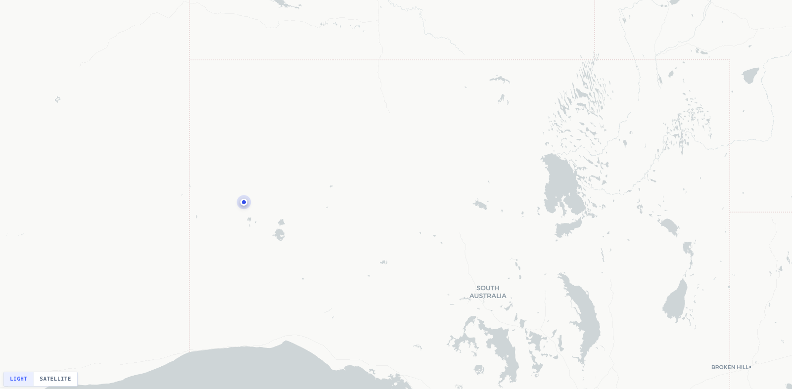
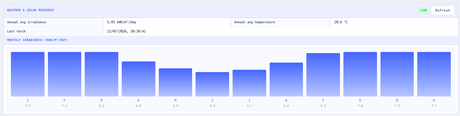
The noIM₃ BESS and Solar System Designer pulls the whole chain into one workspace. The engineer picks a location on an interactive Leaflet map by click, coordinate entry, or Nominatim address search, and a resilient weather service queries the NASA POWER temporal climatology point endpoint for the monthly irradiance and temperature inputs that drive the solar and battery models. Every weather result is tagged as Live, Cached, or Fallback so the provenance of the input data is never in doubt. From there the site inspector walks through Equipment, Solar, Battery, Inverter, and Genset, each backed by its own calculation module, and the load profile produced at the start feeds every downstream stage.

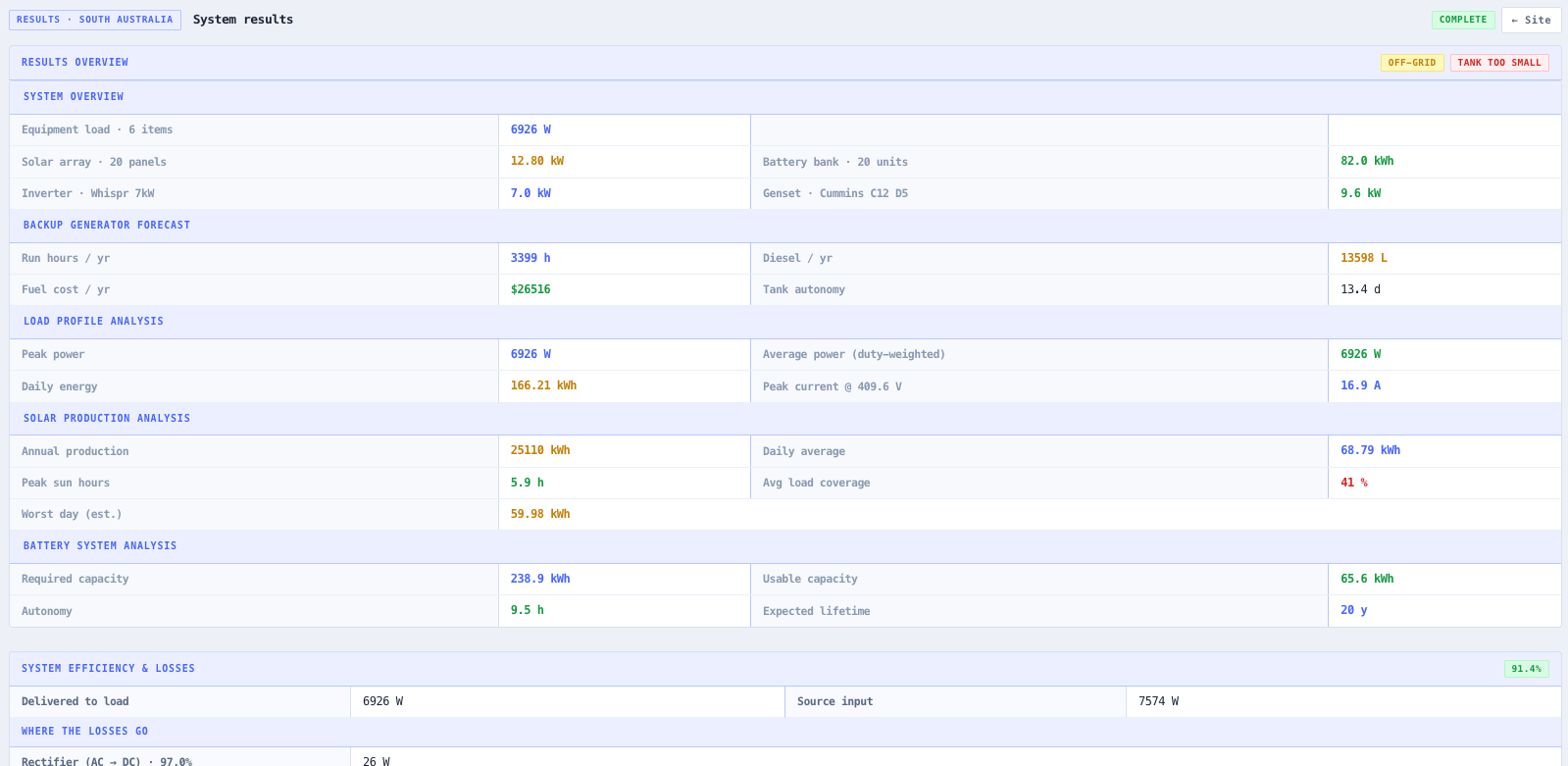
A project is a multi site container (schemaVersion 2 DesignPayload): a single design can hold multiple Sites, each carrying its own full SystemConfiguration scoped to its own map placement, which suits a hub and spoke or multi site rollout. The Results view rolls the active design up into a print optimised report that covers the equipment schedule, the solar production analysis, the battery bank simulation, the monthly energy balance, the per circuit cable and protection schedule, the electrical bill of materials, fault current, arc flash, lightning risk, the AS/NZS compliance findings, the 8760 hour dispatch, the rainflow and Arrhenius ageing projection, and the LCOE, NPV, and payback economics against a diesel only baseline.

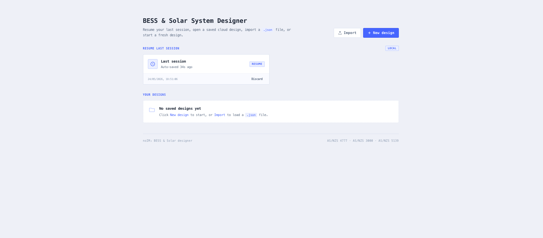
The heaviest computation, the 8760 hour TMY dispatch, runs in a dedicated Web Worker so the main thread stays responsive on the largest projects. Every change is autosaved to browser storage with a visible Saved time ago badge, and named designs can be opened, saved, duplicated, or deleted from the Project Picker. When the design is ready, the whole report exports as an engineering ready PDF for handover, customer review, or licence application.

Capabilities

Multi site project model with named designs

A project is a multi site container (schemaVersion 2 DesignPayload) with one or more Sites, each carrying its own SystemConfiguration scoped to its own map placement. The Project Picker opens, saves, duplicates, and deletes named designs, with the schema version, the site count, and the last saved time visible per design. The active site is selected in the project tree on the Map tab and the inspector works against that site, so a single project can carry a hub and spoke or multi site rollout.

Interactive site selection and NASA POWER climatology

Pick a site on a Leaflet map with click placement, coordinate entry, Nominatim address search, and recent location history. The resilient weather service queries the NASA POWER temporal climatology point endpoint for monthly ALLSKY_SFC_SW_DWN, CLRSKY_SFC_SW_DWN, T2M, T2M_MIN, and T2M_MAX. A browser cache retries on failure, a bundled fallback climatology dataset covers offline use, and every result is tagged as Live, Cached, or Fallback so the engineer always knows where the input data came from.

Equipment load profiling with diversity and power factor

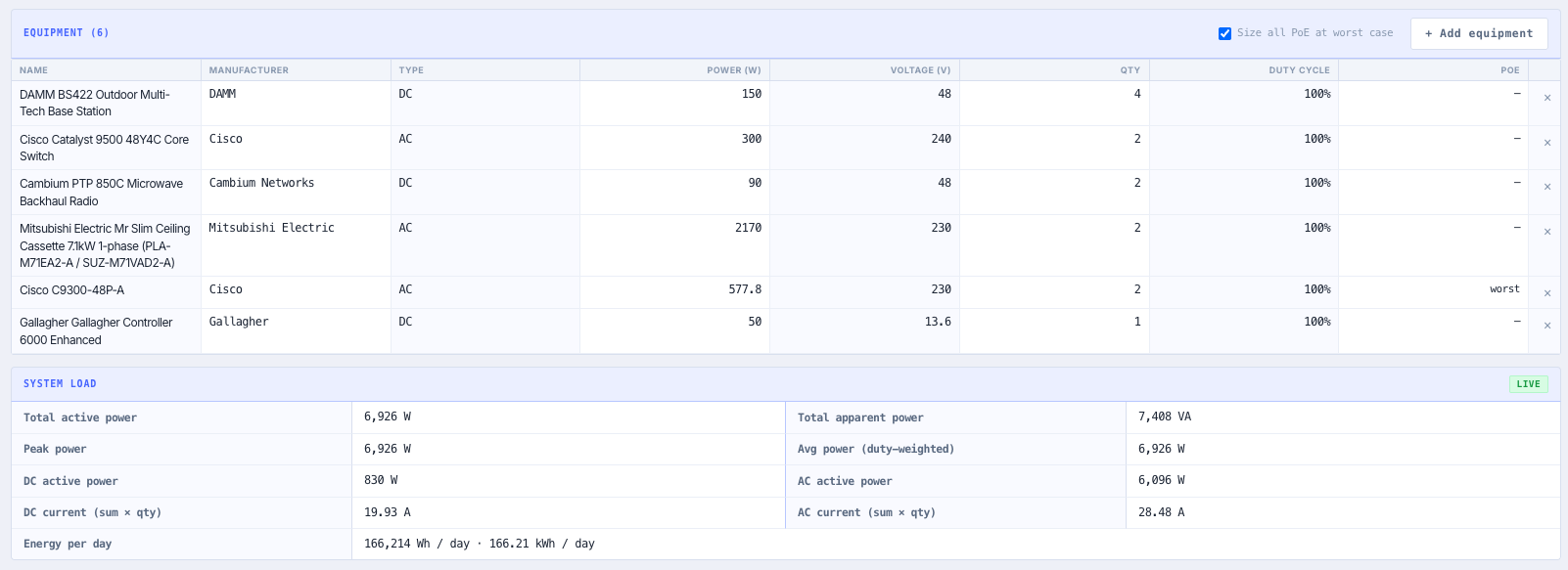
Build the site load from an equipment library (radios, BTS, microwave, routers, HVAC, lighting, monitoring) or add custom entries. Each item carries nominal and surge power, quantity, duty cycle, and power factor. The load engine resolves real versus apparent power (kW and kVA), applies diversity and duty cycle factors, and produces a 24 hour load profile plus peak, average, and daily energy figures that feed solar sizing, the battery bank, the inverter, the cable schedule, and the 8760 hour dispatch.

Solar array sizing, string configuration, and POA transposition

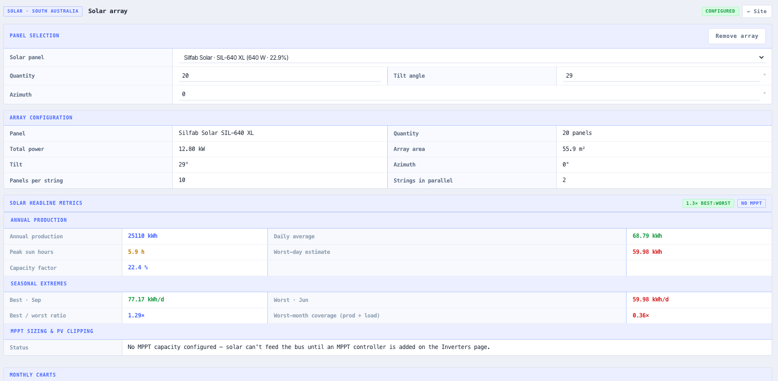
Size the PV array against the daily energy demand using a panel library (Jinko, LONGi, Canadian Solar, and others) with per panel Voc, Vmp, Isc, Imp, temperature coefficients, and NOCT. Auto tilt from latitude and auto azimuth from hemisphere are the defaults with manual override. The solar module validates string series and parallel configuration against the inverter MPPT voltage and current windows, applies a documented loss stack (soiling, mismatch, wiring, inverter, temperature), and runs a Hay Davies style POA transposition for the tilted plane irradiance. Monthly and annual energy yield, capacity factor, and the Inverter Load Ratio are reported.

Battery bank sizing, SoC management, and ageing

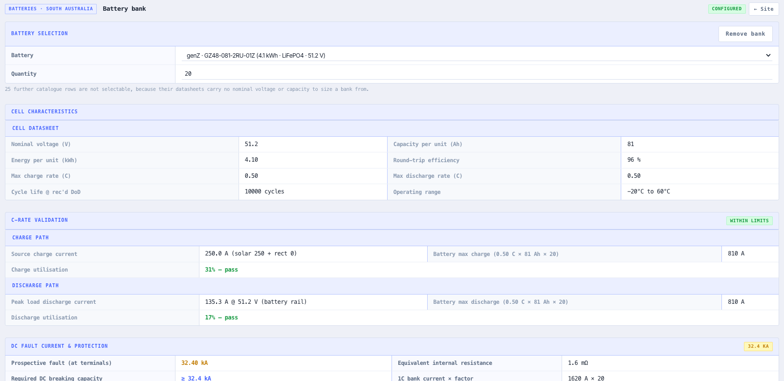
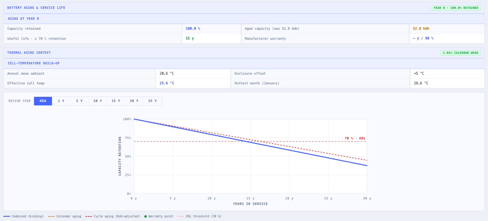
Size the battery bank for autonomy days, depth of discharge target, round trip efficiency, and a minimum state of charge floor. Supports lithium iron phosphate (LFP), nickel manganese cobalt (NMC), and VRLA chemistries from the library with per cell voltage, Ah, Peukert coefficient, and temperature derating. The bank simulation tracks SoC across the TMY year, reports charge time predictions, and estimates lifetime via a hybrid model: Arrhenius calendar ageing driven by the site T2M_MIN and T2M_MAX extremes plus rainflow cycle counting on the simulated SoC trace from the 8760 dispatch.

Modular inverter, rectifier, and solar controller configuration

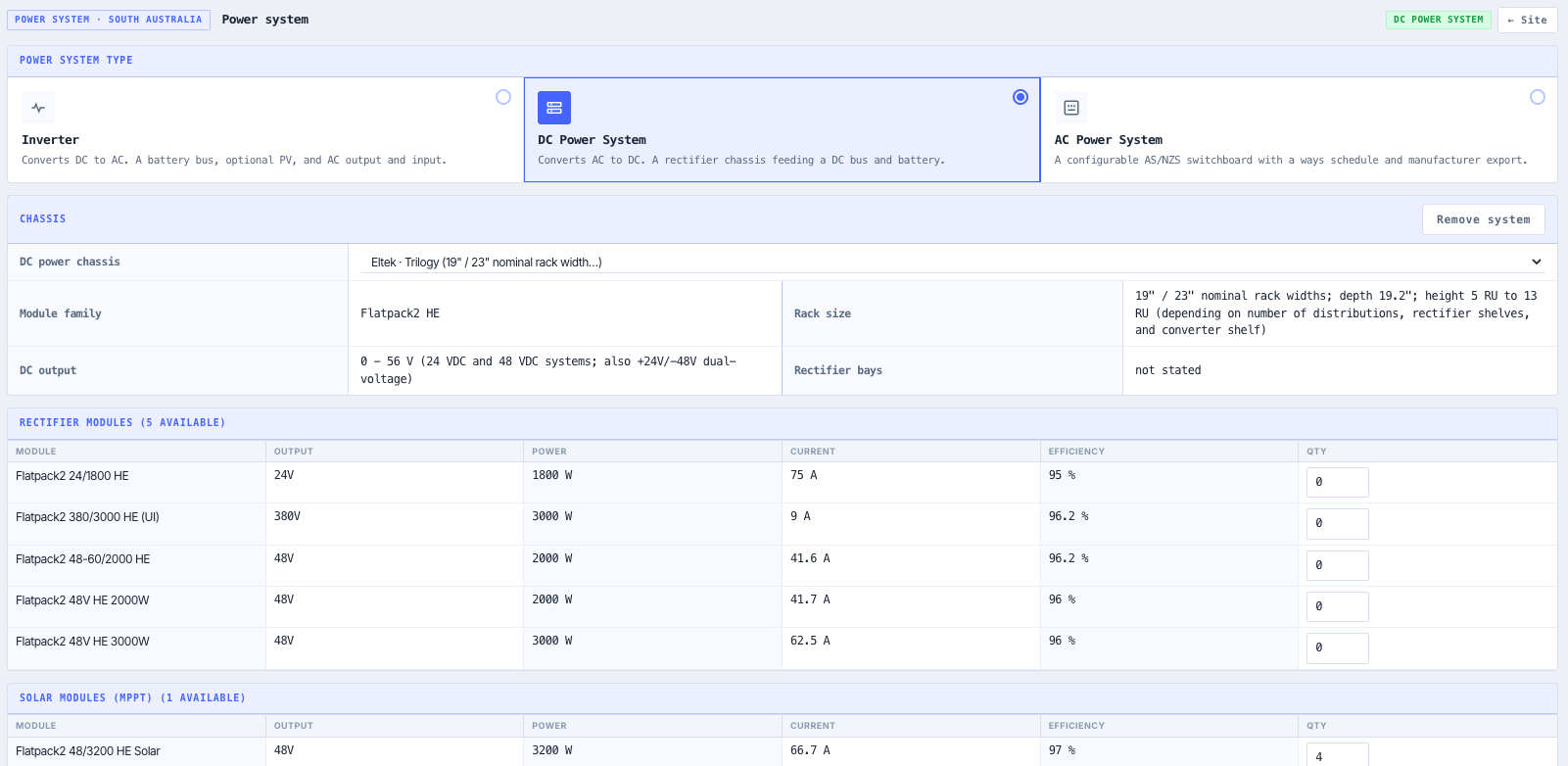
Configure Eltek style modular inverter and rectifier systems from a built in chassis and module database. The inverter service picks module counts for N and N+1 redundancy against the peak and continuous load, validates the DC bus voltage against the battery bank, and pairs the system with compatible MPPT solar controllers. Output includes the full part numbers, the module counts, the input and output ratings, and the redundancy headroom, so an off the shelf bill of materials drops out at the end.

Backup genset selection and dispatch

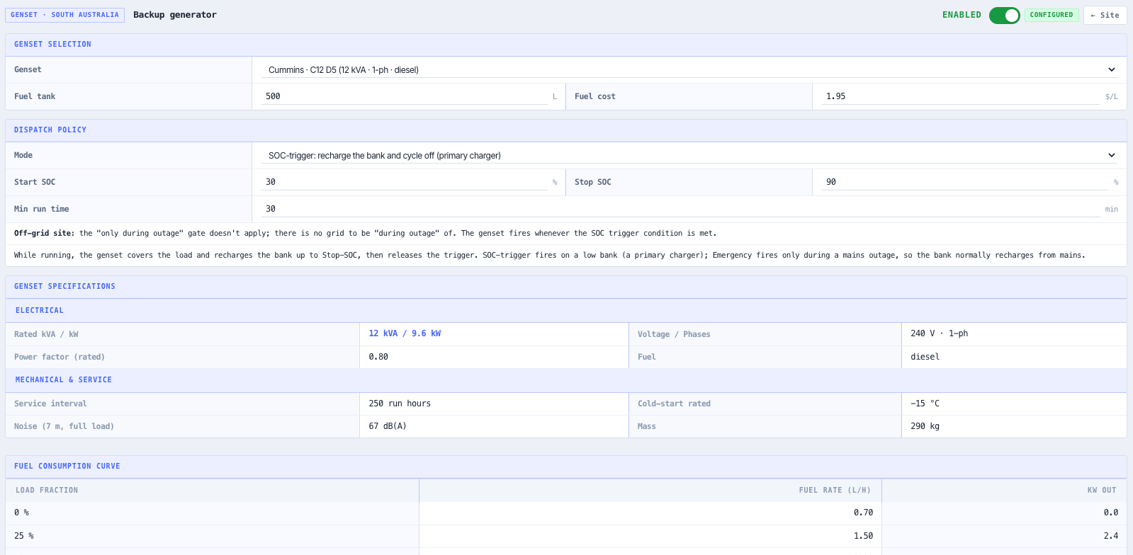
Add a backup diesel generator for hybrid designs from the built in genset database. The dispatch logic runs the generator on top of the solar and battery system to cover unmet load hours, with configurable start triggers (low SoC), stop triggers (SoC recovered, time of day), and a minimum run time. The dispatch is included in the 8760 hour simulation and the fuel burn rolls up into the financial analysis and the diesel only baseline comparison.

Per circuit electrical design to AS/NZS 3000 and 3008.1.1

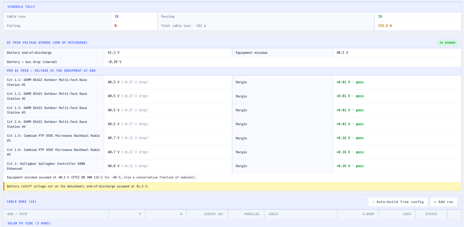
The circuit calculation service generates the full electrical schedule. For every circuit it sizes the cable against AS/NZS 3008.1.1 ampacity tables (copper, 75 degree C column, conduit on wall Method 3), verifies voltage drop to AS/NZS 3000 (typically 5 percent total), selects the protection device (MCB or MCCB) per IEC 60898 and IEC 60947-2, picks a surge protective device per IEC 61643-11, and surfaces the earthing and grounding targets. Each row reports cable size (mm squared), length, current, voltage drop, available fault level, device rating, and a pass or fail flag, culminating in the Electrical Bill of Materials.

Fault current, arc flash, lightning risk, and AS/NZS compliance

Dedicated analysis sections compute the prospective short circuit fault current at each bus, an IEEE 1584 style arc flash incident energy estimate with working distance and PPE category, and a lightning risk score from site geography and exposure. Three compliance modules score the design against AS/NZS 4509 (standalone power systems), AS/NZS 4777 (grid connect inverters), and AS/NZS 5139 (battery installation), each returning a structured pass, warning, or fail list with clause references.

8760 hour dispatch, economics, and PDF export

The dispatch simulation runs the full system across an 8760 hour TMY year in a dedicated Web Worker so the main thread stays responsive: hourly solar production, hourly load, battery charge and discharge with SoC bounds and efficiency, and any generator runtime. The financial module returns the Levelised Cost of Energy (LCOE) in dollars per kWh, the Net Present Value (NPV), simple and discounted payback, and a diesel only baseline comparison for LCOE and CO2. Everything is autosaved and exports as a print optimised engineering PDF.

Standards & methodology

  • AS/NZS 3000 (voltage drop and selection)
  • AS/NZS 3008.1.1 (cable ampacity tables, copper 75 degree C column, Method 3 reference installation)
  • AS/NZS 4509 (standalone power systems)
  • AS/NZS 4777 (grid connect inverter requirements)
  • AS/NZS 5139 (battery installation)
  • IEC 60364
  • IEC 60898 (MCB protection devices)
  • IEC 60947-2 (MCCB protection devices)
  • IEC 61643-11 (surge protective devices)
  • IEEE 1584 style arc flash incident energy

When to use this tool

  • Designing an off grid solar and battery system for a remote radio, telemetry, or repeater site
  • Sizing a hybrid solar plus diesel system with N+1 rectifier redundancy for a telecoms shelter
  • Verifying cable sizing, voltage drop, and protection coordination for a DC and AC distribution board
  • Assessing AS/NZS 4509, 4777, and 5139 compliance before submitting a site package for review
  • Modelling battery bank lifetime under a real load and a real climate using rainflow and Arrhenius
  • Comparing the LCOE, NPV, and payback of a PV plus BESS solution against a diesel only baseline
  • Running an 8760 hour dispatch to quantify unmet load hours and required generator runtime
  • Producing an engineer ready PDF with the full design, schedule, BoM, and compliance findings
  • Evaluating fault current and arc flash hazard at a site switchboard and selecting PPE category
  • Screening lightning risk as part of a site survey and protection scoping
  • Designing a multi site rollout (hub and spoke) where every site carries its own SystemConfiguration
  • Quoting a tender response with a defensible LCOE and a documented engineering schedule

Is this the right tool for you?

Reach for the BESS & Solar System Designer in any of the following situations.

  • You are scoping an off grid solar and battery system for a remote repeater and need the load profile, solar yield, and battery bank sized against the real climate at the site latitude.
  • You are designing a hybrid solar plus diesel telecoms shelter and need N+1 rectifier redundancy plus a genset dispatch that covers the unmet load hours.
  • You need the per circuit cable schedule, voltage drop, and protection coordination to pass AS/NZS 3000 and 3008.1.1 before the design goes out.
  • You are preparing a site package for review and need the AS/NZS 4509, 4777, and 5139 compliance findings with clause references in one document.
  • You want to know how long the battery bank will actually last under the modelled load and the site temperature extremes before you commit to a replacement cadence.
  • You are responding to a tender and need a defensible LCOE, NPV, and payback against a diesel only baseline, backed by a documented engineering schedule.
  • You are rolling out multiple sites in a hub and spoke configuration and want each site to carry its own SystemConfiguration inside a single project.
  • You need an engineering ready PDF of the full design, schedules, bill of materials, compliance findings, and charts for customer review or a licence application.

Frequently asked questions

Where does the weather and solar resource data come from?

The resilient weather service queries the NASA POWER temporal climatology point endpoint for monthly ALLSKY_SFC_SW_DWN, CLRSKY_SFC_SW_DWN, T2M, T2M_MIN, and T2M_MAX at the site location. Responses are cached in browser storage and retried on failure, and a bundled climatology dataset is used as a fallback when the upstream is unavailable. Every result is tagged as Live, Cached, or Fallback on the site card so you always know the provenance of the input data driving the solar and battery calculations.

How is the battery bank lifetime estimated?

Lifetime comes from a hybrid model. Calendar ageing follows the Arrhenius temperature dependent reaction rate driven by the site T2M_MIN and T2M_MAX extremes from the NASA POWER pull, and cycle ageing comes from rainflow counting on the simulated SoC trace produced by the 8760 hour dispatch. The result is reported as projected years of life, equivalent full cycles per year, and a replacement cadence that flows into the financial analysis. The methodology is documented inline so a finance review can see how the figure was derived.

Which electrical standards does the circuit schedule follow?

For every circuit the calculation service sizes the cable against AS/NZS 3008.1.1 ampacity tables (copper, 75 degree C column, conduit on wall Method 3), verifies voltage drop against AS/NZS 3000 (typically 5 percent total), selects the protection device (MCB or MCCB) per IEC 60898 and IEC 60947-2, and picks a surge protective device per IEC 61643-11. Each circuit row reports cable size, length, current, voltage drop, available fault level, device rating, and a pass or fail flag against every check.

What compliance checks are included?

Three compliance modules score the design against the Australian standards. AS/NZS 4509 (standalone power systems) covers autonomy, generator integration, and battery room requirements. AS/NZS 4777 (grid connect inverter requirements) covers inverter behaviour, anti islanding, and voltage and frequency response. AS/NZS 5139 (battery installation) covers enclosure, separation, signage, and ventilation. Each module returns a structured pass, warning, or fail list with clause references.

What does the 8760 hour dispatch simulation produce?

The dispatch runs the full system across an 8760 hour TMY year in a dedicated Web Worker so the main thread stays responsive on the largest projects. It models hourly solar production from the POA transposed irradiance, hourly load from the equipment library, battery charge and discharge with SoC bounds and efficiency, and any backup generator runtime with the configured triggers. Outputs include the SoC time series, the unmet load hours, the generator run hours and fuel burn, and the equivalent full cycles from rainflow counting for the ageing projection.

Can one project hold more than one site?

Yes. A project is a multi site container (schemaVersion 2 DesignPayload). A single design can hold multiple Sites, each carrying its own full SystemConfiguration scoped to its own map placement, with the active site selected in the project tree on the Map tab. This supports hub and spoke and multi site rollout designs where every site is engineered independently inside one project.

How do I get the design out of the tool?

Every change is autosaved to browser storage with a visible Saved time ago badge, and named designs can be opened, saved, duplicated, or deleted from the Project Picker. The Results view is print optimised and exports to PDF, covering the equipment schedule, the circuit schedule, the bill of materials, the compliance findings, the dispatch and ageing charts, and the financial summary in a single document for handover, customer review, or licence application.