Microwave Link Planning

Fresnel Zone Calculator

Line of sight clearance, obstacle analysis, and earth bulge correction for microwave, WISP, and terrestrial RF links. Compute first, second, and third Fresnel zone radii with k factor adjustable earth curvature and the industry 60 per cent F1 clearance rule.

Overview

Line of sight is more than just a clear visual path between two antennas. RF energy travels not as a pencil beam but as an expanding ellipsoid called the Fresnel zone, with the direct ray running through the centre and a region of constructive and destructive interference around it. The first Fresnel zone is the ellipsoid where any reflection or diffraction would arrive at the receiver with a path length difference up to half a wavelength. Industry practice is to keep at least 60 per cent of the first Fresnel zone clear of obstructions for the link to behave as line of sight. Drop below that and diffraction loss starts to dominate the budget. Drop into the second Fresnel zone (50 per cent obstruction) and the link is materially degraded. Total obstruction puts the link into knife edge diffraction territory where the loss is large and unpredictable.

The noIM₃ Fresnel Zone Calculator computes the full ellipsoid geometry at any point along a path. Fn equals square root of (n times lambda times d1 times d2 divided by (d1 plus d2)) for any zone order n and any position along the path. The maximum radius sits at midpath. The 60 per cent F1 clearance line is rendered explicitly. Earth curvature is corrected with the standard effective earth radius model. h bulge equals d1 times d2 divided by (12.75 times k), where k is the refractivity factor (2 over 3 for sub refractive conditions, 1.0 for vacuum or no refraction, 4 over 3 for standard troposphere, 1.5 for super refractive, or any user defined value). Selectable k matches ITU R P.530 recommendations for troposphere propagation.

Path profile visualisation overlays the line of sight ray, first and second Fresnel ellipsoids, earth bulge, and user defined obstacles (trees, buildings, ridges, towers) so diffraction risk is immediately visible. Built in frequency band presets cover 6, 11, 15, 18, 23, 38, and 80 GHz microwave backhaul, 5 GHz ISM, 2.4 GHz WiFi, 900 MHz ISM, and 450 MHz UHF. The clearance dashboard returns pass, caution, or fail against the 60 per cent F1 threshold for every defined obstacle. Useful for microwave backhaul route feasibility, WISP and private LTE link planning, mast height optimisation, tree and building clearance assessment, and validation of terrain studies before site survey.

Capabilities

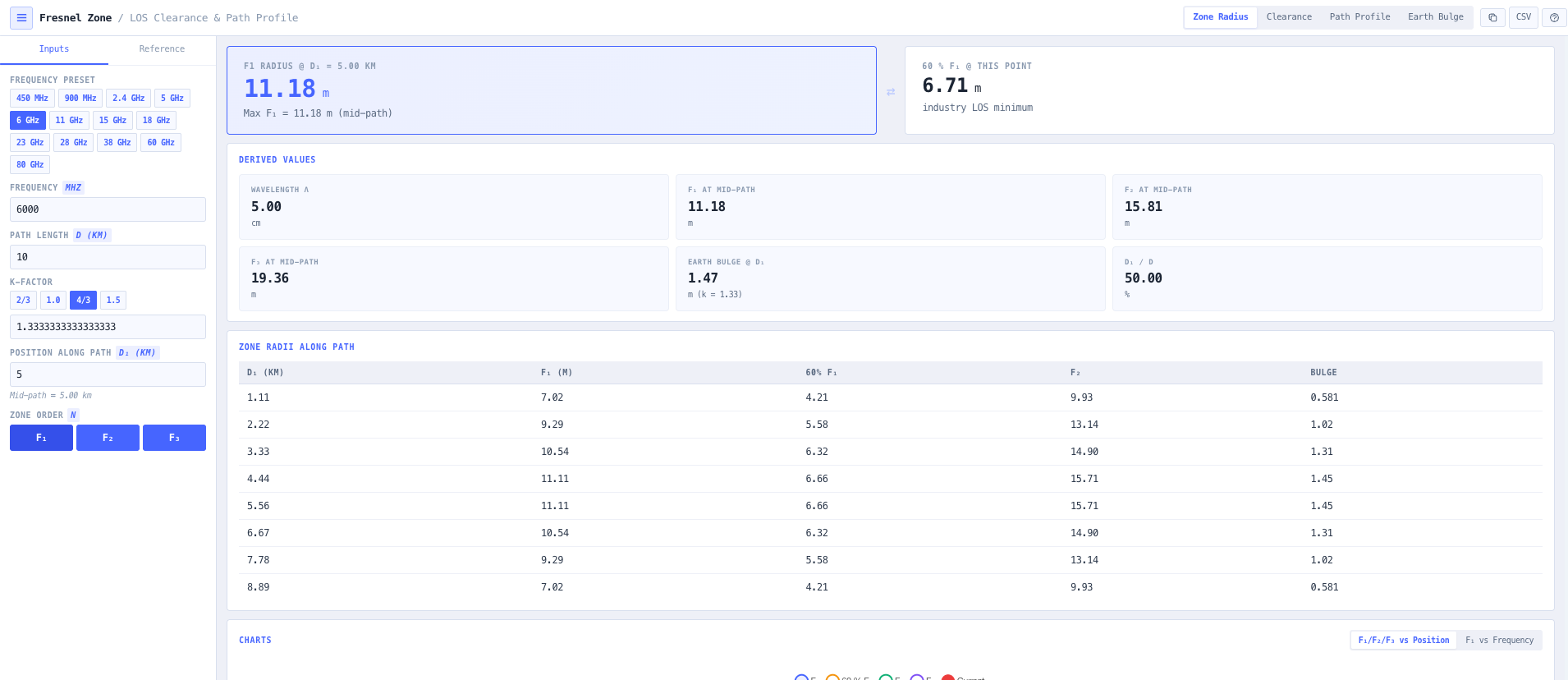
Fresnel zone radius at any point

Computes Fn equals square root of (n times lambda times d1 times d2 divided by (d1 plus d2)) for any zone order n (F1, F2, F3) and any position along the path. Maximum radius at midpath. Radius at user selected offsets along the path. Scaled 60 per cent F1 clearance line rendered explicitly so the industry line of sight minimum is visible directly.

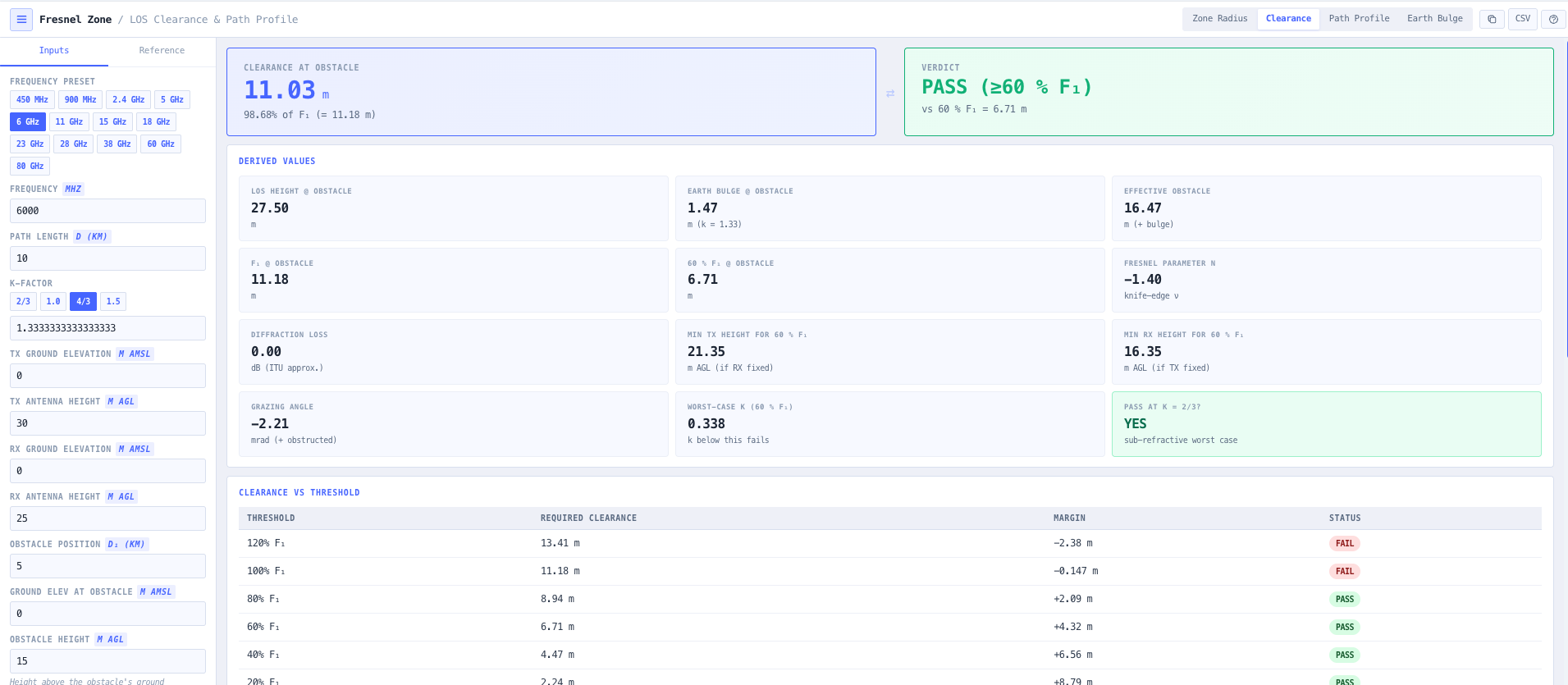
Obstacle clearance analysis

Configure obstacle height and position along the path. The calculator computes available clearance after earth bulge correction, expresses it as a percentage of F1, and reports pass (greater than 60 per cent F1), caution (40 to 60 per cent), or fail (less than 40 per cent) against the line of sight threshold. Useful for tree, building, ridge, and tower clearance checks during route feasibility assessment.

Earth bulge with k factor selection

Earth curvature correction using the standard effective earth radius model. h bulge equals d1 times d2 divided by (12.75 times k) for distances in km and bulge in metres. Selectable k factor presets covering sub refractive (2 over 3), no refraction (1.0), standard troposphere (4 over 3), super refractive (1.5), and any user defined value. Matches ITU R P.530 recommendations for terrestrial line of sight propagation.

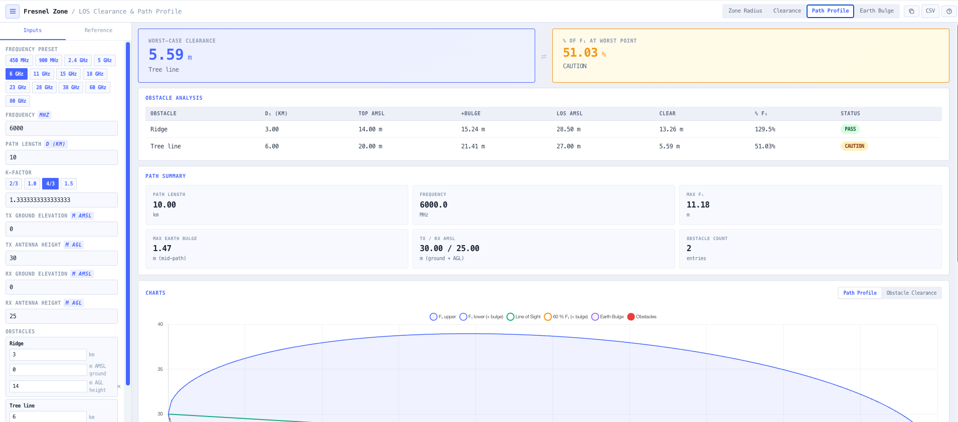
Multi obstacle path profile

Render the full path profile with the line of sight ray, first Fresnel ellipsoid, second Fresnel zone, earth bulge curve, and any number of user defined obstacles overlaid. Obstacles are placed by distance and height and the calculator returns clearance per obstacle. Useful for ridge crossing assessment, tree line evaluation, and confirming whether mast height adjustments will achieve the 60 per cent F1 minimum.

Frequency band presets

Built in presets for 6, 11, 15, 18, 23, 26, 38, and 80 GHz microwave backhaul, 5 GHz ISM, 2.4 GHz WiFi, 900 MHz ISM, and 450 MHz UHF. Each preset populates frequency for the common configuration so the route feasibility check is one click. Manual entry remains available for unusual frequencies, millimetre wave, and sub GHz applications.

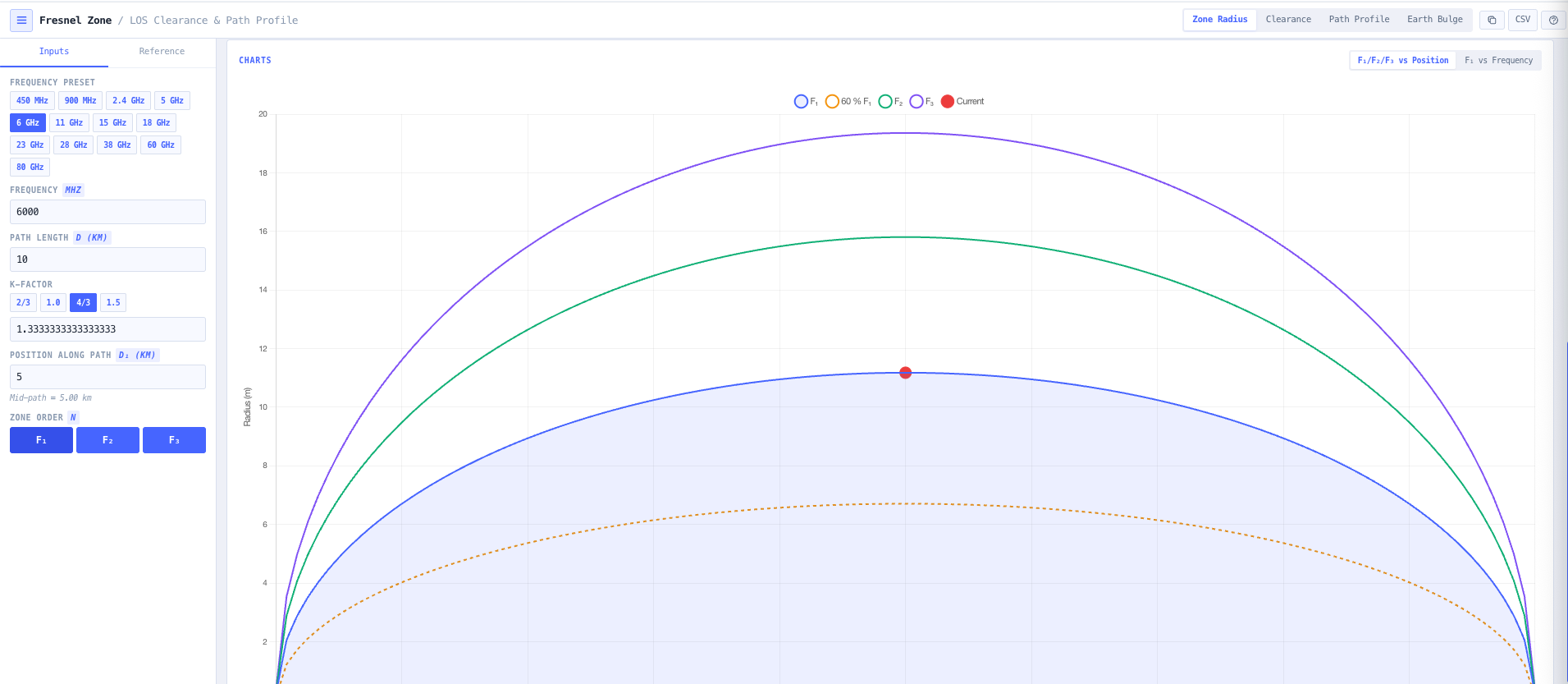
Visualisation and tables

Interactive charts cover Fresnel radius versus position along the path, full path profile with obstacles overlaid, clearance versus frequency at the same path geometry (showing how higher frequency improves Fresnel clearance for the same physical clearance), and earth bulge versus k factor (showing how refractivity changes the effective bulge). Tables break down clearance at each zone order and at common percentage thresholds (60, 80, 100 per cent).

Mid path and offset radius reporting

Maximum Fresnel radius at midpath is the headline number for path planning. The calculator additionally reports the radius at any user selected offset along the path, useful when the critical obstacle is not at the midpoint (a ridge near one end of the path, a tree line at a known offset, a tower or building at a measured distance from one site).

Line of sight pass or fail dashboard

Single glance pass, caution, or fail status against the 60 per cent F1 line of sight threshold for every defined obstacle. Combined with the path profile visualisation, the dashboard makes route feasibility immediately obvious and supports the design discussion around mast height, route deviation, or alternative site selection.

Browser only computation

Runs entirely in your browser. No path geometry, obstacle data, or link parameters are submitted to a server. Useful for commercially confidential infrastructure planning, defence and security site work, and environments where information security policy prohibits sending engineering data to third party services.

Standards & methodology

  • ITU R P.530. Propagation data and methods for terrestrial line of sight systems
  • ITU R P.526. Propagation by diffraction
  • ITU R P.453. The radio refractive index for ground based and slant paths
  • ITU R P.834. Effects of tropospheric refraction on radiowave propagation
  • Industry 60 per cent of first Fresnel zone clearance rule for line of sight links
  • Standard effective earth radius factor k equals 4 over 3 for typical troposphere

When to use this tool

  • Microwave backhaul route feasibility assessment from 6 to 80 GHz
  • Wireless ISP (WISP) and private LTE or 5G NR link planning
  • Mast height optimisation for line of sight clearance
  • Tree, building, ridge, and tower obstruction assessment
  • Earth curvature correction for long path terrestrial links
  • Aeronautical and maritime line of sight link design
  • Educational visualisation of Fresnel ellipsoid geometry
  • Validation of terrain study output against the 60 per cent F1 rule
  • Sanity checking vendor proposed microwave link routes against independent geometry
  • Producing engineering evidence for ACMA microwave licence applications
  • Sub refractive ducting risk assessment using lower k factor scenarios
  • Identifying which obstacle along a multi obstacle path drives the route feasibility

Is this the right tool for you?

Reach for the Fresnel Zone Calculator in any of the following situations.

  • You are planning a microwave or millimetre wave backhaul link and need to confirm that the candidate route maintains 60 per cent F1 clearance at the operating frequency over the configured path length.
  • You are evaluating a WISP or private LTE point to point link and want to verify line of sight clearance against tree lines, ridges, and buildings along the path before survey.
  • You are sizing mast heights at each end of a microwave link and need to know the minimum height combination that delivers 60 per cent F1 clearance over the worst obstacle.
  • You are responding to a working microwave link that is failing during sub refractive conditions and want to evaluate the path with k equals 2 over 3 to confirm whether the earth bulge predicts loss of clearance.
  • You are validating a vendor proposed microwave route against independent Fresnel geometry before committing to procurement and tower mounting.
  • You are producing engineering evidence for an ACMA microwave licence application that requires a documented path profile with Fresnel clearance against terrain.
  • You are diagnosing intermittent microwave link availability that correlates with weather and want to confirm whether the path was already marginal on Fresnel clearance under standard atmosphere.
  • You are evaluating multiple candidate routes for the same end points and want a side by side Fresnel clearance comparison against terrain and obstacle data.
  • You are planning an aeronautical or maritime line of sight link and need accurate earth bulge correction over long over water paths.
  • You are training new RF engineers in microwave link planning and want a teaching tool that visualises the Fresnel ellipsoid and the 60 per cent F1 rule against real obstacles.
  • You are evaluating whether to remove or top a tree line that intrudes into the Fresnel zone of a working link and need to confirm the exact clearance required.
  • You are responsible for a national microwave network and need a fast Fresnel feasibility check before requesting a full ITU P.530 link planning pass on each candidate route.
  • You are checking a temporary or event microwave link against the underlying Fresnel geometry before deployment.
  • You are responsible for a fixed wireless access deployment in a regional or remote Australian area and need terrain aware Fresnel clearance against actual ridge and tree line heights.
  • You are operating under a security regime that prohibits sending route data to third party services and need a Fresnel zone calculator that runs entirely in your browser.

Frequently asked questions

What is a Fresnel zone?

A Fresnel zone is an elliptical region around the direct ray between transmitter and receiver where any reflected or diffracted ray would arrive with a path length difference up to a particular fraction of a wavelength. The first Fresnel zone uses a half wavelength bound. The second uses a full wavelength. The third uses 1.5 wavelengths. The first Fresnel zone is the dominant contributor to the link, which is why industry practice is to keep at least 60 per cent of the first Fresnel zone clear of obstructions for the link to behave as line of sight.

What is the formula?

Fn equals square root of (n times lambda times d1 times d2 divided by (d1 plus d2)), where n is the zone order, lambda is the wavelength, d1 is the distance from the transmit end to the point of interest, and d2 is the distance from that point to the receive end. Maximum at midpath where d1 equals d2 equals d over 2. The 60 per cent F1 line equals 0.6 times F1 at any point along the path.

Why 60 per cent of F1?

It is the industry rule of thumb derived from theoretical analysis of diffraction loss as a function of obstruction depth. With less than 60 per cent F1 clearance, diffraction loss is essentially zero. Between 60 and 100 per cent F1 obstruction, diffraction loss is small but not negligible. At full F1 obstruction (touching the line of sight), the link is at knife edge and loss is around 6 dB. Beyond that, the link is in deep diffraction and loss grows quickly. The 60 per cent threshold is the practical line above which the link behaves as line of sight under typical atmospheric variation.

How is earth curvature handled?

Earth bulge is computed using the standard effective earth radius model. h bulge equals d1 times d2 divided by (12.75 times k) for d1 and d2 in km and bulge in metres. The k factor accounts for atmospheric refraction. Standard troposphere is k equals 4 over 3, which extends the effective earth radius and bends the radio ray slightly. Sub refractive conditions (k around 2 over 3) shrink the effective radius and increase the apparent bulge. Super refractive conditions (k around 1.5) extend the effective radius. The calculator supports k presets covering all the common conditions plus user defined values.

When does sub refractive matter?

Sub refractive conditions (k less than 1) occur when the troposphere refractivity gradient inverts, typically during temperature inversions and certain weather patterns. The apparent earth bulge increases, which can take a marginal link below the 60 per cent F1 threshold and produce diffraction loss that knocks the link out. Designing the link with k equals 2 over 3 (or worse) as a worst case confirms whether the route survives the bad atmosphere or only works under standard troposphere. ITU R P.530 is the reference for this practice.

How does this support microwave link planning?

Fresnel clearance is the first feasibility check on any microwave route. Pass the 60 per cent F1 rule against k equals 4 over 3 and the link is line of sight. Survive k equals 2 over 3 and the link is robust. Use the noIM₃ Link Planner for full ITU P.530 link design with terrain accurate path profiles from Mapbox global Terrain RGB DEM, automatic ITU model coverage (P.526, P.530, P.676, P.838, P.840, P.2108), and full provenance for every input. The Fresnel Zone Calculator covers fast feasibility. The Link Planner covers full design.

What if my critical obstacle is not at midpath?

The maximum Fresnel radius is at midpath, but the critical obstacle is often not at the midpoint. The calculator returns Fresnel radius at any user selected offset along the path, so you can evaluate clearance against a tree line at 30 per cent of the path, a ridge at 70 per cent, or a building at a known distance. The pass or fail dashboard handles each obstacle independently against its position.

Does any data leave my browser?

No. The calculator runs entirely in your browser. No path geometry, obstacle data, or link parameters are submitted to a server. Useful for commercially confidential infrastructure planning, defence and security site work, and environments where information security policy prohibits sending engineering data to third party services.