Network Design

Structured Cabling Channel Planner

Check a twisted-pair run against the permanent link and channel length limits. Enter the fixed horizontal cable and the cords, de-rate for temperature and cord length, and see which Ethernet applications the run will carry.

Overview

Every twisted-pair install turns on one question: is the run inside the length limits, and what will it carry. A balanced cabling link is measured two ways. The channel is the full end-to-end connection of fixed horizontal cable plus the patch, equipment and work-area cords, with a reference maximum of 100 m. The permanent link is the fixed horizontal cable and its connectors alone, the part that stays in the wall, with a reference maximum of 90 m. The classic split is 90 m of horizontal plus 10 m of cords, but two things eat into that 90 m: the operating temperature, because insertion loss rises with heat, and the length of the flexible cords, because stranded cords are lossier per metre than solid horizontal cable.

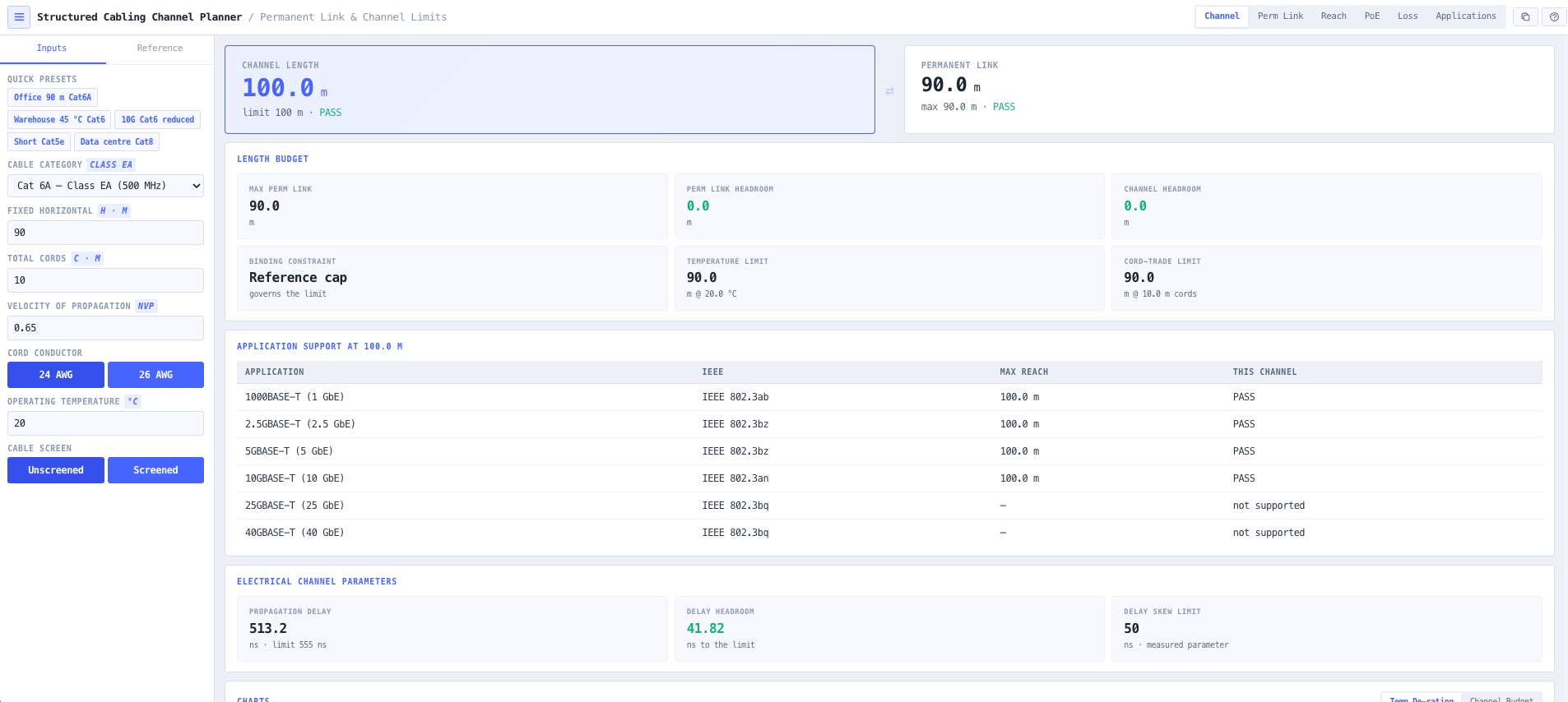
You pick the category, from Cat 5e through Cat 8, enter the fixed horizontal cable length and the total cord length, and set the operating temperature and whether the cable is screened. The tool reports the channel and permanent link lengths against their limits, the de-rated maximum horizontal length, the headroom, and which of the three constraints, the 90 m cap, the temperature de-rating or the cord trade, is governing. It also lists which BASE-T applications the run will carry, from 1000BASE-T through 10GBASE-T and, for Cat 8, 25 and 40GBASE-T.

It works the other way too. If you know the speed you need, the Reach mode inverts the question and reports the maximum length that still delivers it over each category, de-rated for temperature. A speed inside a category band reaches the full 100 m, so the length only falls below that where a cable is pushed past its band, such as 10GBASE-T over Cat 6 at 37 to 55 m, or Cat 8 at 30 m. It makes choosing the category for a target speed and distance a single look.

A run is bound by more than length. The Channel mode also reports the propagation delay against the 555 ns limit and the 50 ns delay skew limit, a dedicated PoE mode sizes power over the cabling (DC loop resistance against the 25 ohm limit, voltage drop and far-end power for the port current, the real I squared R cable self-heat, and the bundle-heat de-rating where a temperature rise added to ambient shortens the run and the TIA TSB-184-A 15 degree design cap is kept in view), and a Loss mode plots the channel insertion loss limit against frequency and checks a measured loss against it for the margin, using formulas validated against their published anchors.

It is scoped for the installer and designer sizing a run, not for frequency-swept insertion-loss, NEXT or return-loss certification, which is what a field tester does against the cable on the wall. No cable datasheet figures are invented. The length model is the generic cabling model that AS/CA S009:2020 Appendix L mandates for Australian customer cabling, and the tool cites that basis openly.

Capabilities

Two length limits tracked

The channel, fixed horizontal plus cords, against its 100 m limit, and the permanent link, the fixed horizontal alone, against its 90 m limit. Both are reported with the headroom, so an over-length run is caught before the cable is pulled, not after a failed certification.

Temperature de-rating to the standard

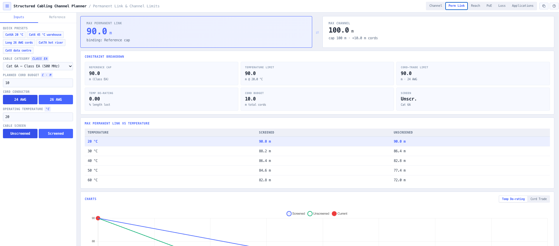
Insertion loss rises with temperature, so the maximum length falls above 20 degrees. Screened cable loses 0.2 percent of length per degree over 20 to 60 degrees, unscreened cable loses 0.4 percent per degree to 40 degrees and 0.6 percent per degree beyond. A hot ceiling void or warehouse roof space is de-rated to the length the cable can carry.

The cord-length trade

Stranded cords are lossier per metre than solid horizontal cable, so longer or 26 AWG cords force a shorter fixed horizontal length. The tool applies the ISO and TIA cord trade, C equals 102 minus H divided by 1 plus the cord de-rating factor, and shows the binding constraint against the 90 m cap and the temperature limit.

Ethernet application support

A length that passes the channel limit does not always carry the application you want. The tool lists every BASE-T application against the channel length with its IEEE standard and maximum reach, including the reduced 10GBASE-T reach over Cat 6 and the Cat 8 25 and 40GBASE-T support to 30 m.

Speed to length, the inverse lookup

Know the speed, need the length. Reach mode takes a target speed and reports the maximum length that still delivers it over each category, de-rated for temperature. The per-category table makes the trade plain: 10GBASE-T reaches 100 m on Cat 6A but only 37 to 55 m on Cat 6, and 25 and 40GBASE-T reach 30 m on Cat 8. It is the fast way to pick the category a run needs for a speed and a distance.

PoE over the cabling

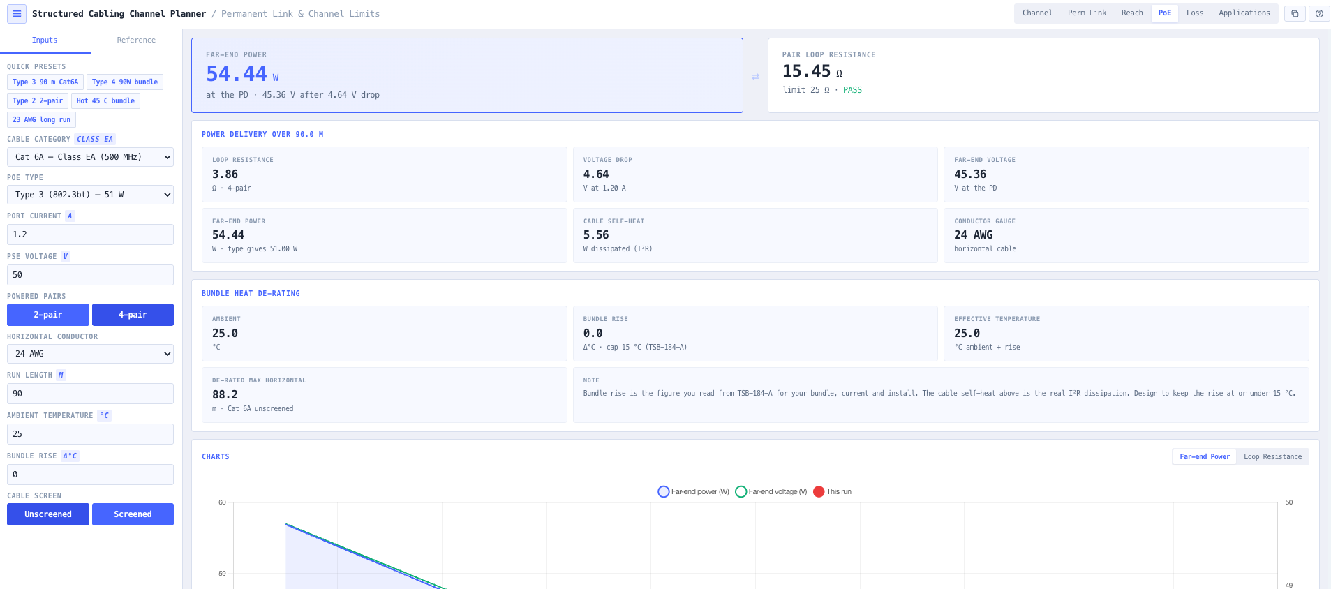
A dedicated PoE mode sizes power delivery. Pick a PoE type, conductor gauge and run length and read the DC loop resistance against the 25 ohm limit, the voltage drop, and the power at the far end. Bundle heating adds a temperature rise to ambient that de-rates the maximum length: enter the rise from TSB-184-A for your bundle and current, and the tool shows the real I squared R self-heat and holds the 15 degree design cap in view.

Electrical channel parameters

Length is not the only limit. The Channel mode reports the propagation delay against the 555 ns channel limit, computed from the length and the velocity of propagation, and the 50 ns delay skew limit, so a long or slow run that would fail on delay is caught alongside the length checks.

Insertion loss limit and margin

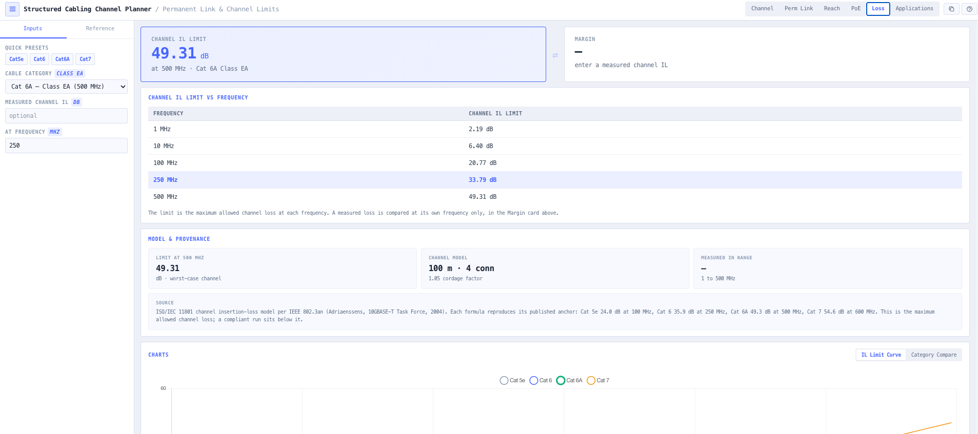
The Loss mode plots the worst-case channel insertion loss limit against frequency for the category, from the ISO/IEC 11801 channel model, and checks a measured or datasheet channel loss against it for the margin. Every formula is validated against its published anchor, so Cat 6A reads 49.3 dB at 500 MHz to the decimal. Cat 7A and Cat 8 are excluded rather than approximated, because no validated free-source formula was available.

Honest about the standard

AS/CA S009:2020 is the Australian Wiring Rules and does not itself carry the insertion-loss tables. Its Appendix L gives the 90 m rule and directs the reader to AS/NZS 11801.1 for de-rating. The length model here is AS/NZS 11801.1 / ISO/IEC 11801-1, mirrored in ANSI/TIA-568.2, and the tool cites that basis rather than claiming S009 carries tables it does not.

Browser only computation

Runs entirely in your browser. Nothing about your design is submitted to a third party service, which suits commercially confidential work and any environment where information security policy prohibits sending engineering data off site. The per-run summary copies to the clipboard for a cable schedule or test plan.

Standards & methodology

  • AS/CA S009:2020 Installation requirements for customer cabling (Wiring Rules), Appendix L (90 m horizontal rule and direction to de-rate for heat and application)
  • AS/NZS 11801.1 / ISO/IEC 11801-1 Information technology, generic cabling for customer premises (channel and permanent link length model, temperature and cord de-rating)
  • ANSI/TIA-568.2 Balanced twisted-pair telecommunications cabling and components (mirrored length, cord-trade and electrical channel model: 25 ohm DC loop resistance, 555 ns propagation delay, 50 ns delay skew)
  • TIA TSB-155 / ISO/IEC TR 24750 (10GBASE-T reduced reach over Class E / Cat 6)
  • TIA TSB-184-A / ISO/IEC TR 29125 (PoE bundle temperature rise, 15 degree design cap)
  • IEEE 802.3an channel insertion loss model (Adriaenssens, 10GBASE-T Task Force) for the ISO/IEC 11801 channel insertion loss limit, validated against published anchors
  • IEEE 802.3 (1000BASE-T, 2.5/5GBASE-T, 10GBASE-T, 25/40GBASE-T application reach; PoE Types 1 to 4)

When to use this tool

  • Checking a horizontal run plus its cords against the 90 m and 100 m limits before pulling cable
  • De-rating the maximum length for a hot ceiling void, plant room or warehouse roof space
  • Working out how much a long or 26 AWG cord budget shortens the permitted horizontal length
  • Deciding whether a Cat 6 run will carry 10GBASE-T and at what reduced reach
  • Choosing the cable category a new run needs for a target Ethernet speed and length
  • Setting the maximum horizontal pull length for a design before the cable goes in
  • Confirming a Cat 8 data-centre link is inside the 30 m channel and 24 m permanent link limits
  • Documenting the length budget and application support of a run for a cable schedule

Frequently asked questions

What is the difference between a permanent link and a channel?

The permanent link is the fixed part of the run, the horizontal cable and its connectors, that stays in the building fabric, with a reference maximum of 90 m. The channel is the full end-to-end connection including the patch, equipment and work-area cords, with a reference maximum of 100 m. The classic split is 90 m of fixed horizontal plus 10 m of cords, and this tool reports both against their limits.

Why does the maximum length drop with temperature?

Insertion loss in a twisted-pair cable rises with temperature, so a run that passes at the 20 degree reference can fail when it is hot. The standard de-rates the maximum length accordingly: screened cable loses 0.2 percent per degree over 20 to 60 degrees, and unscreened cable loses 0.4 percent per degree from 20 to 40 and 0.6 percent per degree from 40 to 60. A run through a hot roof space is de-rated to the length the cable can actually carry.

Why do longer patch cords shorten the horizontal cable?

Stranded flexible cords are lossier per metre than the solid horizontal cable, so a longer or thinner cord budget spends more of the loss allowance and leaves less for the horizontal. The ISO and TIA cord trade, C equals 102 minus H divided by 1 plus the cord de-rating factor, gives the maximum horizontal length for a given cord budget, using 0.2 for 24 AWG cords and 0.5 for the lossier 26 AWG cords.

Does this tool certify a cabling link?

No. Certification is a frequency-swept measurement of insertion loss, NEXT, return loss and related parameters against the installed cable, done with a field tester. This tool is a design-stage length planner: it checks the permanent link and channel lengths against the limits, de-rates for temperature and cords, and lists the applications the length supports. It does not model swept insertion loss and does not replace a tester.

Is this based on S009?

AS/CA S009:2020 is the Australian Wiring Rules. It gives the 90 m horizontal rule in Appendix L and directs the reader to AS/NZS 11801.1 for length restrictions arising from heat and application, but it does not itself carry the insertion-loss and length tables. The length model in this tool is therefore AS/NZS 11801.1 / ISO/IEC 11801-1, mirrored in ANSI/TIA-568.2, which S009 Appendix L mandates for Australian customer cabling. The tool cites this basis rather than claiming S009 carries the model.

Which Ethernet speeds can each category carry?

1000BASE-T and 2.5GBASE-T run to 100 m on Cat 5e, 5GBASE-T runs to 100 m on Cat 6, and 10GBASE-T runs to 100 m on Cat 6A but only to a reduced reach on Cat 6, 37 m unqualified and up to 55 m with alien-crosstalk mitigation. 25 and 40GBASE-T run on Cat 8 to 30 m. The tool lists each application with its maximum reach so the category and the length are chosen together.

Does it check insertion loss, and where do the limits come from?

Yes. The Loss mode plots the worst-case channel insertion loss limit against frequency for the category and checks a measured or datasheet channel loss against it for the margin. The limits are the ISO/IEC 11801 channel model as broken down by the IEEE 802.3an 10GBASE-T task force: a 100 m cable term with a 1.05 cordage factor plus four connectors. Every formula is validated against its published anchor to the decimal, so Cat 5e reads 24.0 dB at 100 MHz, Cat 6 35.9 dB at 250 MHz, Cat 6A 49.3 dB at 500 MHz and Cat 7 54.6 dB at 600 MHz. Cat 7A and Cat 8 are not included: a validated free-source formula was not available and no coefficients are invented for them. It is a design-stage limit and margin view, not a substitute for a field tester sweep.

Can it size PoE over the cabling, including bundle heating?

Yes. The PoE mode reports the DC loop resistance against the 25 ohm channel limit, the voltage drop and the power delivered at the powered device for the port current, and the real I squared R self-heat of the cable. Bundle heating is handled the way TIA TSB-184-A frames it: a PoE cable bundle self-heats above ambient, and that temperature rise de-rates the maximum length. You enter the rise you read from TSB-184-A for your bundle size, current and install, the tool adds it to ambient and de-rates the length, and the 15 degree design cap is kept in view. The proprietary TSB-184-A thermal table is not reproduced or invented; the tool computes the physics it can and takes the rise as your input.

I know the speed I need. What is the maximum length I can run it?

That is what Reach mode is for. Pick the target speed and the tool reports the maximum length that still delivers it over each category, de-rated for the operating temperature. A common misconception is that a higher speed always shortens the run on the same cable: in fact a speed inside a category band reaches the full 100 m, so 2.5GBASE-T, 5GBASE-T and 10GBASE-T all reach 100 m on Cat 6A. The length only drops below 100 m where a cable is pushed past its band, such as 10GBASE-T over Cat 6 at 37 to 55 m, or Cat 8 at 30 m, plus whatever heat de-rating removes. Reach mode shows exactly where that happens.