Network Design

Structured Cabling Designer

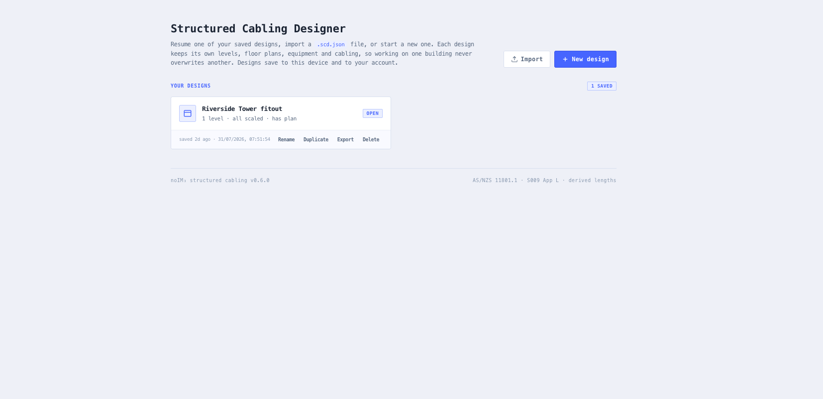
Design a building’s structured cabling on real floor plans. Place racks, patch panels, switches and outlets at real coordinates, route the cable the way it actually runs, and let every length and every permanent link check derive from the layout rather than from a spreadsheet.

Overview

A structured cabling design turns on one number: how long the run is. Everything downstream depends on it. Inside 90 m the permanent link passes, past it the run fails certification and someone re-pulls a cable through a closed ceiling. And that number is the one a spreadsheet cannot know, because it is set by a route through the building that has not been walked yet.

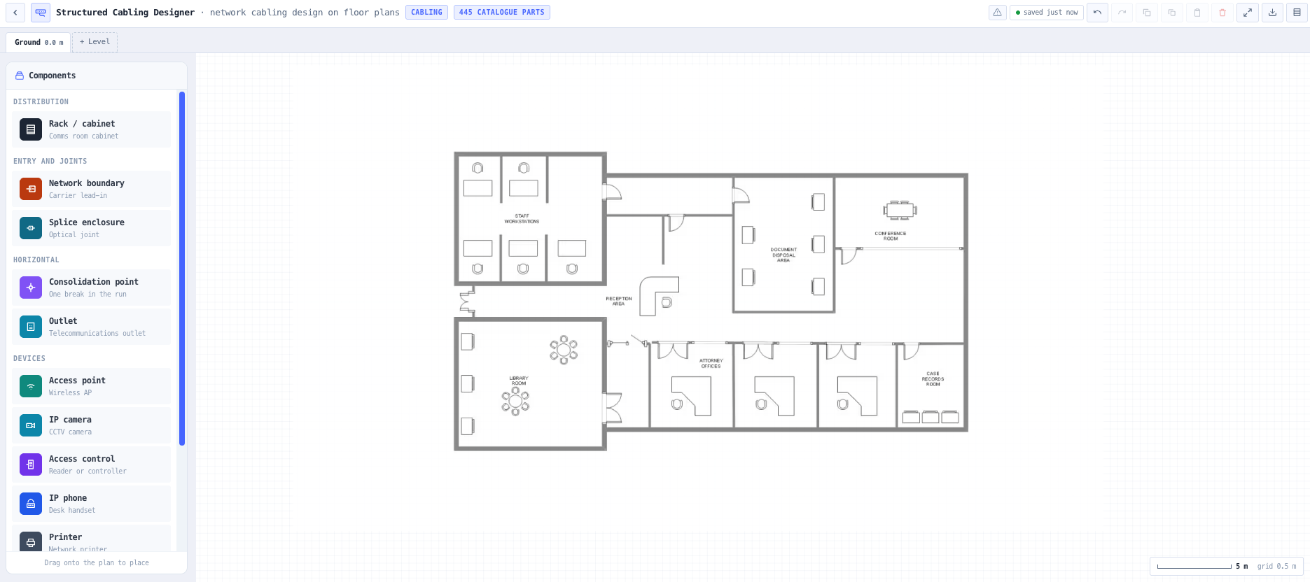
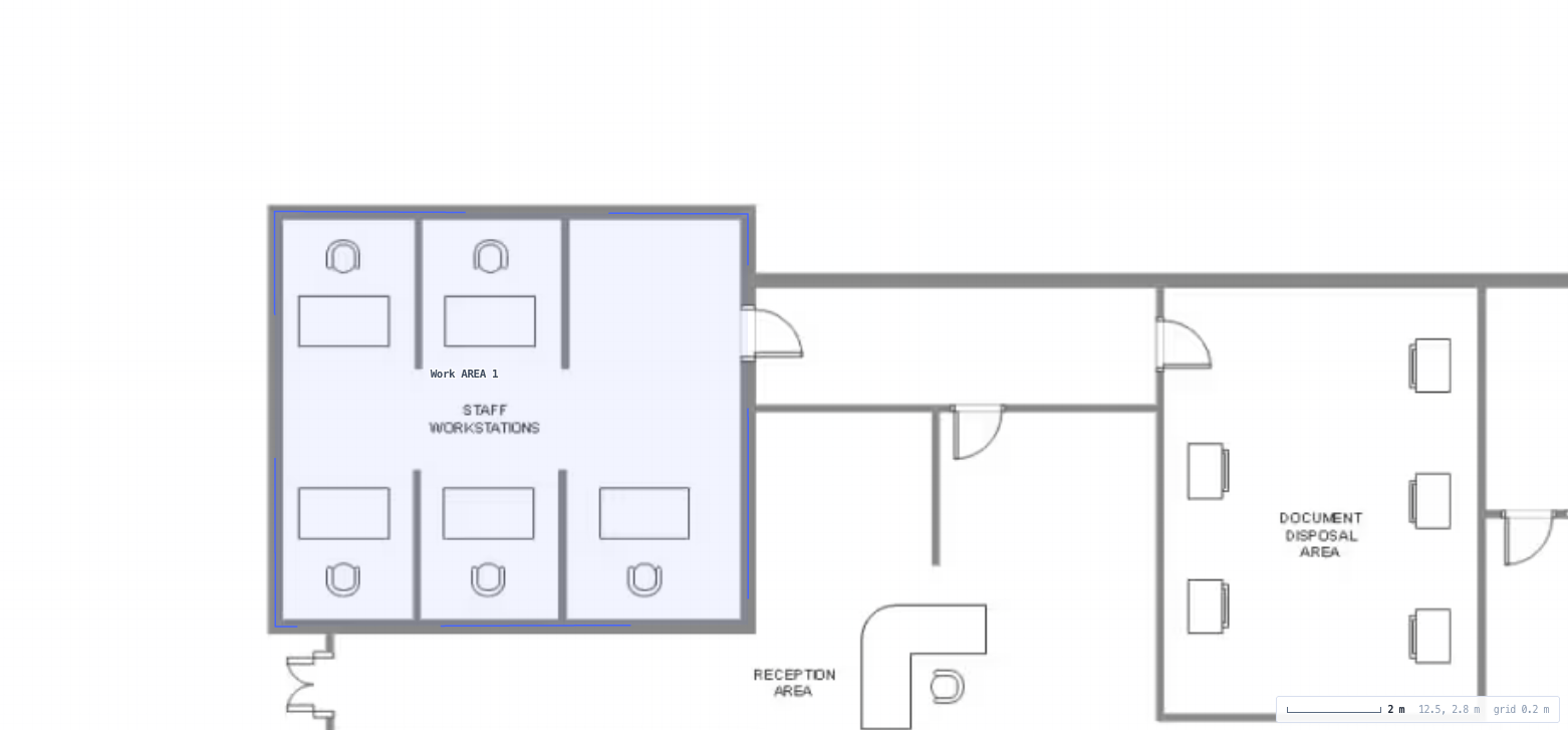
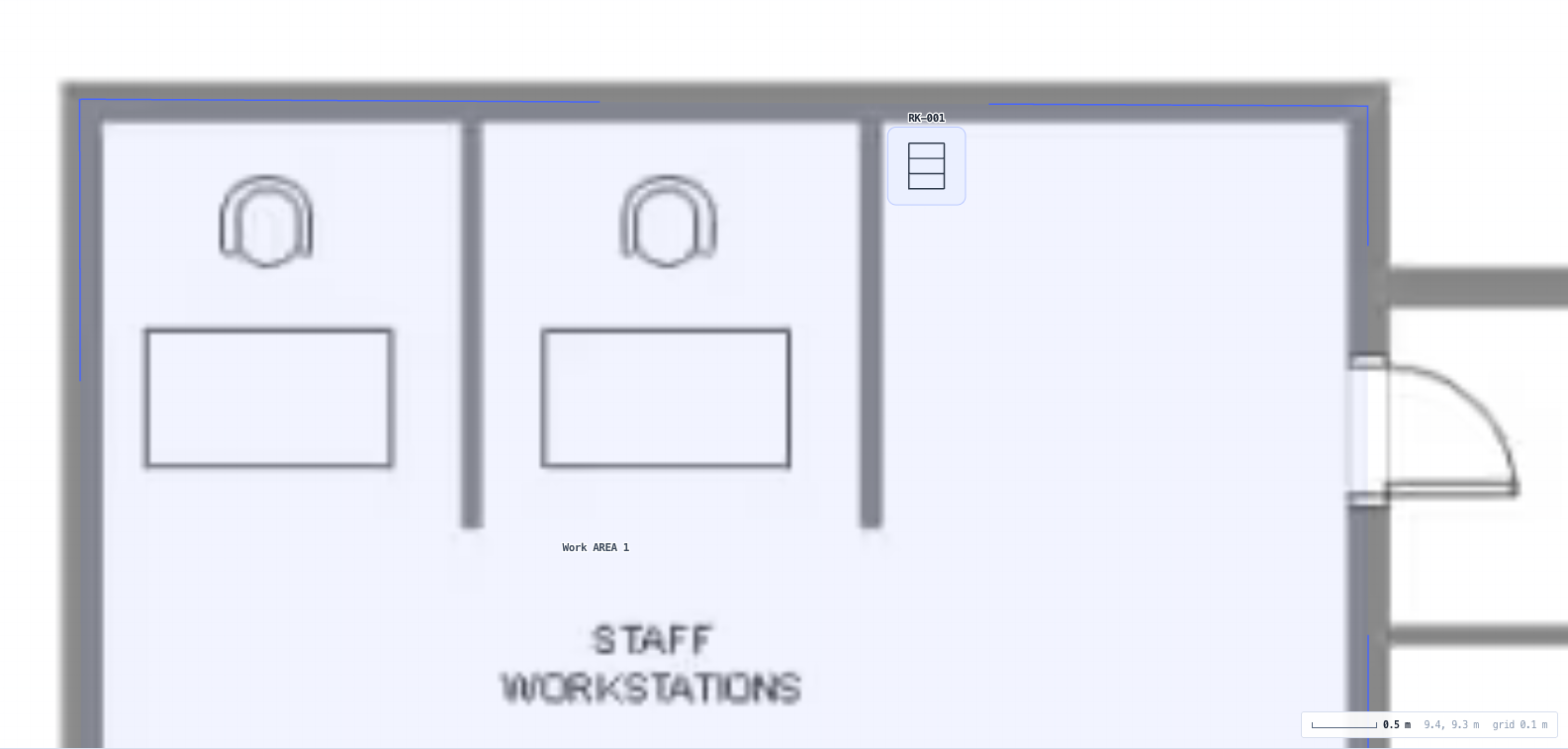
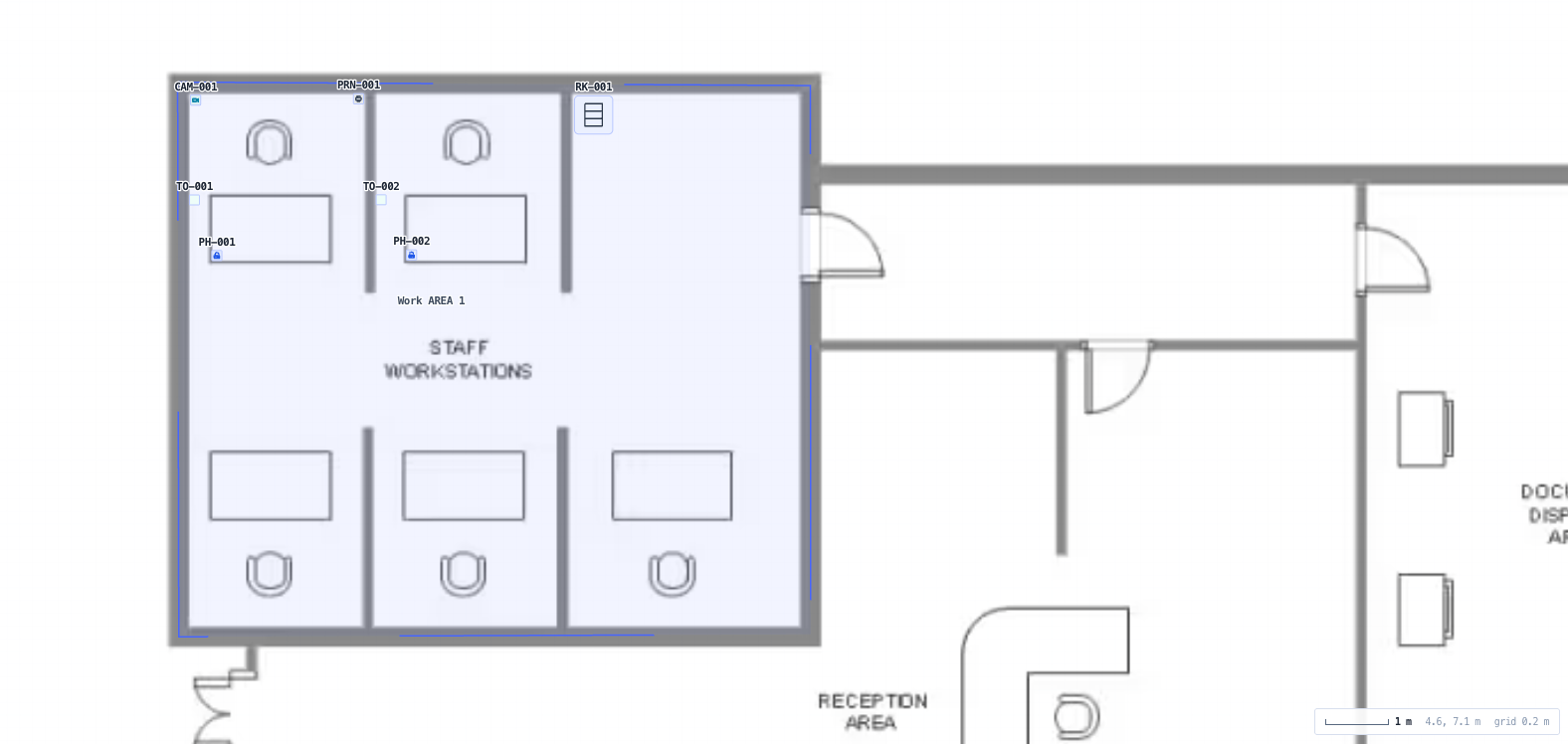
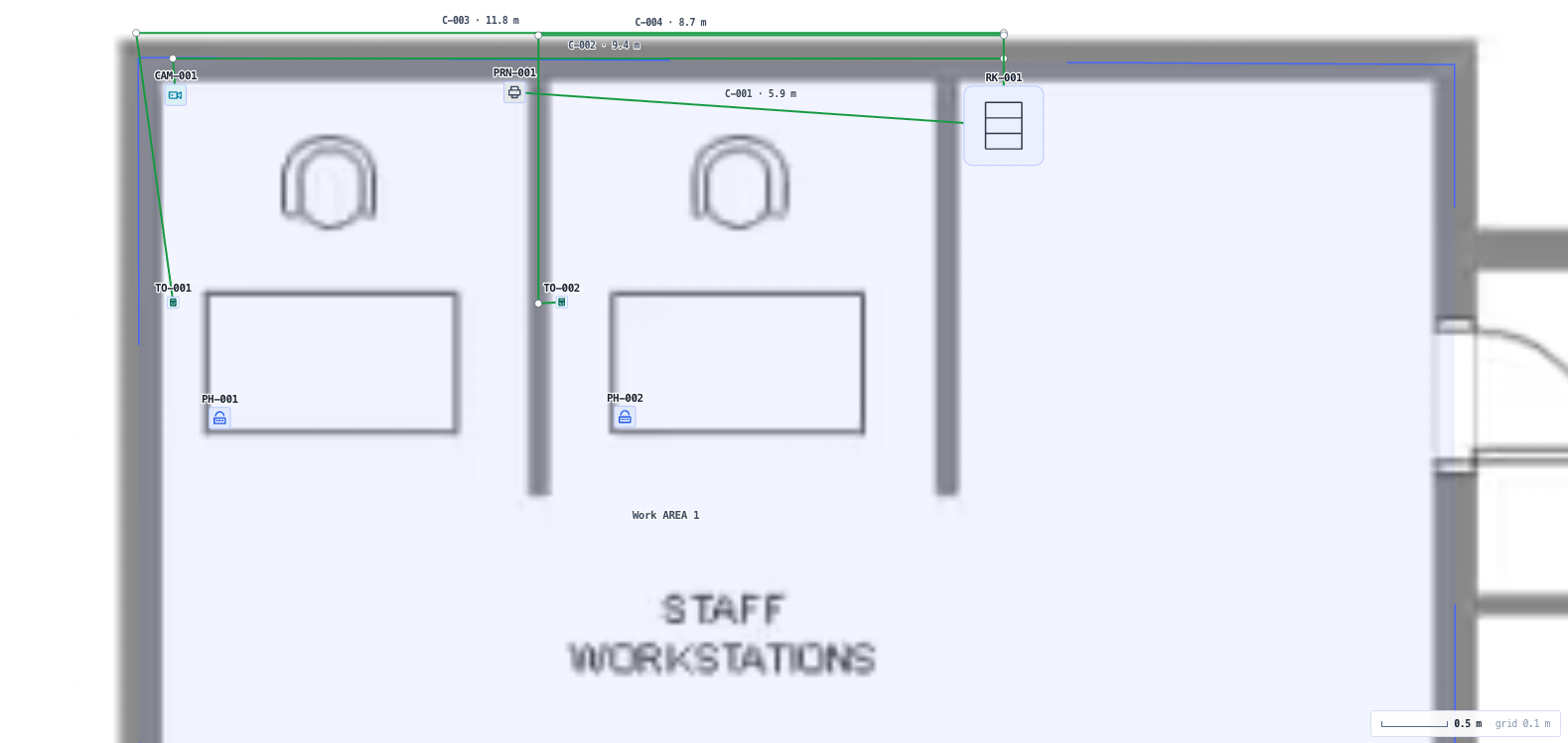
So the design happens on the floor plan. Import a plan image per level, set its scale by clicking two points a known distance apart or by dragging the plan against the grid, then place racks, patch panels, switches, consolidation points, outlets and end devices at real metre coordinates. Draw each cable run the way the cable actually goes, around the core and along the tray, and the length comes from that route: the horizontal, plus the vertical when it climbs a riser between levels, plus a service loop at each end, plus the slack you set for dressing. Where someone has already been on site with a tape, the measured length replaces the derived one and suppresses the slack, because a real measurement already contains it.

Each run is then checked against both limits, the permanent link and the channel, using exactly the length model that drives the free Structured Cabling Channel Planner. It is imported rather than reimplemented, so the two tools cannot disagree about the same run. The maximum is de-rated for the operating temperature the cable actually sees and traded against the cord budget you declare, and the result names which of the three constraints is binding, so it is clear what would have to change. A run that passes the length limit but will not carry the speed its device needs fails too, which is the case that otherwise surfaces at commissioning.

It is a design stage planner, not a certifier. There is no frequency swept insertion loss, NEXT, return loss or alien crosstalk modelling, and it does not replace a field tester or the compliance obligations carried by an ACMA registered cabler.

Capabilities

Length derived from the route, not typed in

Run lengths come from the geometry you drew. Waypoints take a run around a core or along a tray, a run between levels picks up the vertical from the floor elevations, and a per end service loop plus a slack allowance you control cover dressing and termination. The length is broken into routed, riser, service loop and slack so the parts reconcile against the total and the figure can be argued with rather than just accepted.

A measured length replaces the estimate

Enter a length measured on site and it becomes the length, with the slack and the service loops suppressed rather than added on top, because a tape measure already contains both. The run is badged as measured so nobody has to guess which figures came from a walk and which from the drawing.

Permanent link and channel checked per run

Both limits are reported against their own maxima, with the headroom and the binding constraint: the fixed cap, the temperature de-rating or the cord budget. The cord allowance you declare is spent against the channel and never quietly reduced to make an over length run fit.

The same length model as the free Channel Planner

The model is imported from the Structured Cabling Channel Planner rather than reimplemented, so the two tools can never diverge about the same run. That planner remains the right tool for one run in isolation. This one exists for the case it cannot serve: several hundred runs whose lengths are set by a route nobody has measured yet.

Application support, not just a length pass

Each run reports the BASE-T applications its channel will carry, including the reduced 10GBASE-T reach over Class E. A run inside 90 m that will not deliver the speed its camera or access point needs is failed with the reach and the channel length both stated, at the point where the category can still be changed for the cost of a line item.

Capacity and provisioning

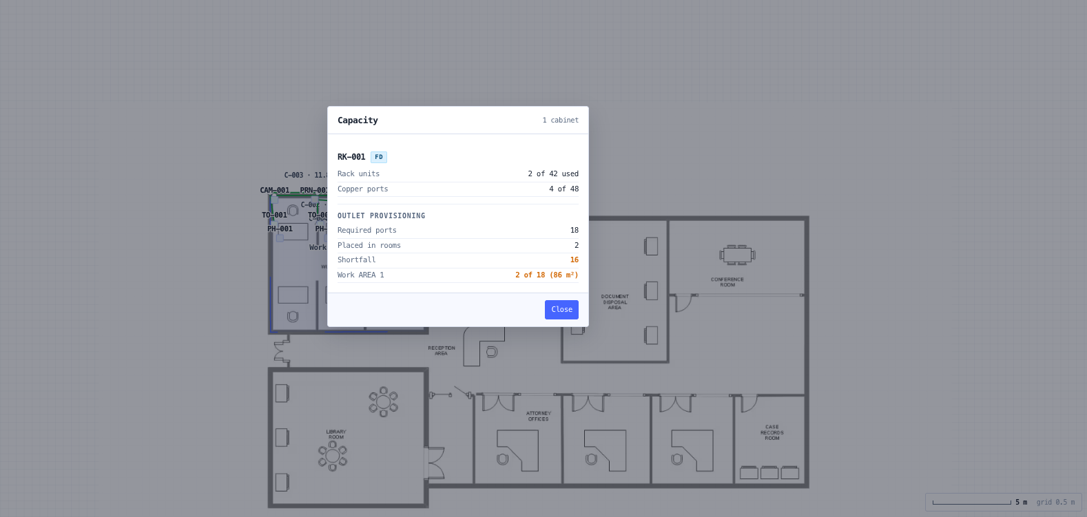
Rack units used against each cabinet, copper and optical positions, switch ports, and the shortfall against the spare policy you set. Uplink oversubscription per switch, computed from the ports actually patched rather than the ports fitted. Outlet provisioning measured over the work areas you drew, at a density you set, with plant rooms and risers excludable.

Real hardware, honestly labelled

Switches, IP cameras, access control hardware and optical cable load from the noIM₃ component catalogue alongside a generic planning library. A catalogue row that does not record enough to make a usable part is listed with the reason rather than admitted with a guess, and every part carries a badge saying whether its numbers come from a datasheet or from a clearly labelled generic.

Cannot check is a real verdict

A run on a level whose plan has no scale, on media that cannot be resolved, or carrying optical fibre is reported as unchecked rather than quietly passed, and unchecked is counted apart from passed. An unscaled plan would otherwise produce lengths in the wrong unit that are compared against 90 m and pass everything.

Validation that refuses to guess

A run terminating on a port that does not exist, two runs on one port, a run to a deleted component, a part of the wrong kind, an outlet nobody cabled, a level carrying equipment with no scale set, or a powered device fed by a switch that cannot supply power. Each is reported and clickable rather than computed around.

The documents the design implies

Cable schedule, port and patching matrix, and equipment list with bill of materials, each derived from the same model rather than retyped from it and each exportable as CSV. The schedule is shaped for the Cable Schedule Generator and the equipment list for the Equipment List Generator.

Standards & methodology

  • AS/NZS 11801.1 / ISO/IEC 11801-1 Information technology, generic cabling for customer premises (channel and permanent link length model, temperature and cord de-rating)
  • ANSI/TIA-568.2 Balanced twisted-pair telecommunications cabling and components (mirrored length and cord-trade model)
  • AS/CA S009:2020 Installation requirements for customer cabling (Wiring Rules), Appendix L, which mandates the generic cabling length model for Australian customer cabling. S009 does not itself carry the insertion-loss or length tables
  • ISO/IEC 11801 / ANSI/TIA-568.2 channel DC loop resistance limit of 25 ohm for Class D and above, over solid annealed copper conductor resistance scaled by the copper temperature coefficient
  • TIA TSB-155 / ISO/IEC TR 24750 (10GBASE-T reduced reach over Class E / Cat 6)
  • IEEE 802.3 (1000BASE-T, 2.5/5GBASE-T, 10GBASE-T, 25/40GBASE-T application reach)

When to use this tool

  • Designing the horizontal and backbone cabling for a commercial fit out
  • Finding the corner of a building where the runs will not make the 90 m permanent link
  • Sizing the maximum horizontal pull length on each level before any cable is ordered
  • Producing the cable schedule and port matrix for a tender or a design and construct submission
  • Checking that a Cat 6 refresh will carry the speed the new access points need
  • Laying out comms rooms and working out how many patch panels and rack units each one needs
  • Cabling an IP camera and access control rollout across an existing building
  • Checking outlet provisioning across the work areas against the density the client asked for
  • Reworking a design when the tenancy layout changes and every run length changes with it
  • Producing an as built cable schedule for handover documentation

Frequently asked questions

How is this different from the Structured Cabling Channel Planner?

The Channel Planner answers "will this one run pass", with the length typed in. It is free and it remains the right tool for a single run. This one answers "what runs does this building need, where do they go, how long are they, and do they all pass", with the length derived from a floor plan. They share the same length model: it is imported rather than reimplemented, so the two tools cannot disagree about the same run.

Where does the run length come from?

From the route you drew. The horizontal is the polyline through the waypoints you placed, so a run taken around a core or along a tray is billed for the distance it actually covers rather than the straight line between its ends. A run between levels adds the difference in floor elevation for the riser. A service loop is added at each end and a slack percentage you set covers dressing. Every part is shown separately and they sum to the total.

Can I set a different service loop on one run?

Yes. The design carries a default, because most runs are dressed the same way, and any individual run can override it. How much cable is coiled at each end is decided cable by cable: a loop above a ceiling tile at an access point is not the several metres left in a cabinet so a panel can be re-terminated later. The override is on the run itself, it feeds the derived length and therefore the compliance check, and setting it to zero is a decision the tool keeps rather than reading as blank.

Does it check anything other than length?

Yes. Length is the constraint that binds most often, but it is not the only channel requirement, so the channel pair loop resistance is checked as well: the horizontal cable and the cords summed at their own conductor gauges, at the operating temperature of that run, against the 25 ohm channel limit. It can fail a run that passed the length check, which is exactly the case worth catching, since loop resistance is what governs how much power over Ethernet survives the cable. Where the conductor gauge on a part is not one the model covers, the figure is withheld rather than guessed. Propagation delay and delay skew are not checked here: they need a velocity factor the catalogue parts do not carry, and at any realistic figure they cannot be breached inside a 100 m channel.

What happens if I enter a measured length?

It replaces the derived figure entirely, and the slack and service loops drop to zero rather than being added on top. A length measured with a tape already contains the dressing and the loops, so adding an allowance would double count it and push a passing run towards a fail. The run is badged as measured.

Does it certify the cabling?

No. Certification is a frequency swept measurement of insertion loss, NEXT, return loss and related parameters against the installed cable, done with a field tester. This is a design stage planner: it checks lengths against the limits, de-rates for temperature and cords, and lists the applications the length supports. It does not replace a tester, and it does not discharge the obligations of an ACMA registered cabler.

What does cannot check mean?

That the tool could not evaluate the run honestly, so it is not claiming a result. The common cases are a level whose plan has no real scale, media that cannot be resolved to a part, and optical fibre, which is budgeted for loss rather than limited by length. Cannot check is counted apart from pass everywhere it appears, because a run the tool could not evaluate has not been shown to be compliant.

Does it budget optical backbone links?

Not in this build. An optical run is placed, routed, scheduled and its length derived like any other, but it is not loss budgeted and reports cannot check rather than a verdict. The reason is data: the optical cable rows in the component catalogue are mechanical and carry no attenuation coefficient, and building the check would mean inventing both the coefficient and the class limit to compare it against.

Are the cable identifiers to AS/NZS 3085.1?

No. The identifiers use this tool’s own readable convention, combining the level, the component and the port so a physical label stays legible. AS/NZS 3085.1 specifies identifier formats and this tool does not claim conformance to it. If the site has an existing identifier scheme, follow that.

Can I use real hardware rather than generic parts?

Yes. Switches, IP cameras, access control hardware and optical cable load from the noIM₃ component catalogue alongside the generic planning library, so a design already using a generic part keeps working and you choose per component. A catalogue row that does not record enough to make a usable part, such as a switch with no port count, is listed with the reason rather than offered as though it were usable.