Microwave Link Planning

Link Budget Calculator

End to end RF link budget for any wireless system. EIRP, received power, total path loss, fade margin, noise floor, and carrier to noise ratio in one workspace covering VHF and UHF land mobile, WiFi, LTE, satellite, and microwave links.

Overview

A link budget is the engineering document that decides whether a wireless link will actually work in service. Every dB on the path between transmitter and receiver is accounted for. Transmit power. Antenna gains at each end. Cable, connector, and feeder losses. Free space path loss. Atmospheric absorption from oxygen and water vapour. Rain attenuation. Foliage, diffraction, and clutter loss. Polarisation mismatch. Fade margin to absorb time varying effects. The result is a received power against a receiver sensitivity threshold, with a link margin in dB telling you how much headroom remains. Build the budget right and the link runs through every realistic operating condition. Build it badly and the link works in the lab and fails the moment it rains, the leaves come out, or the path absorbs water vapour.

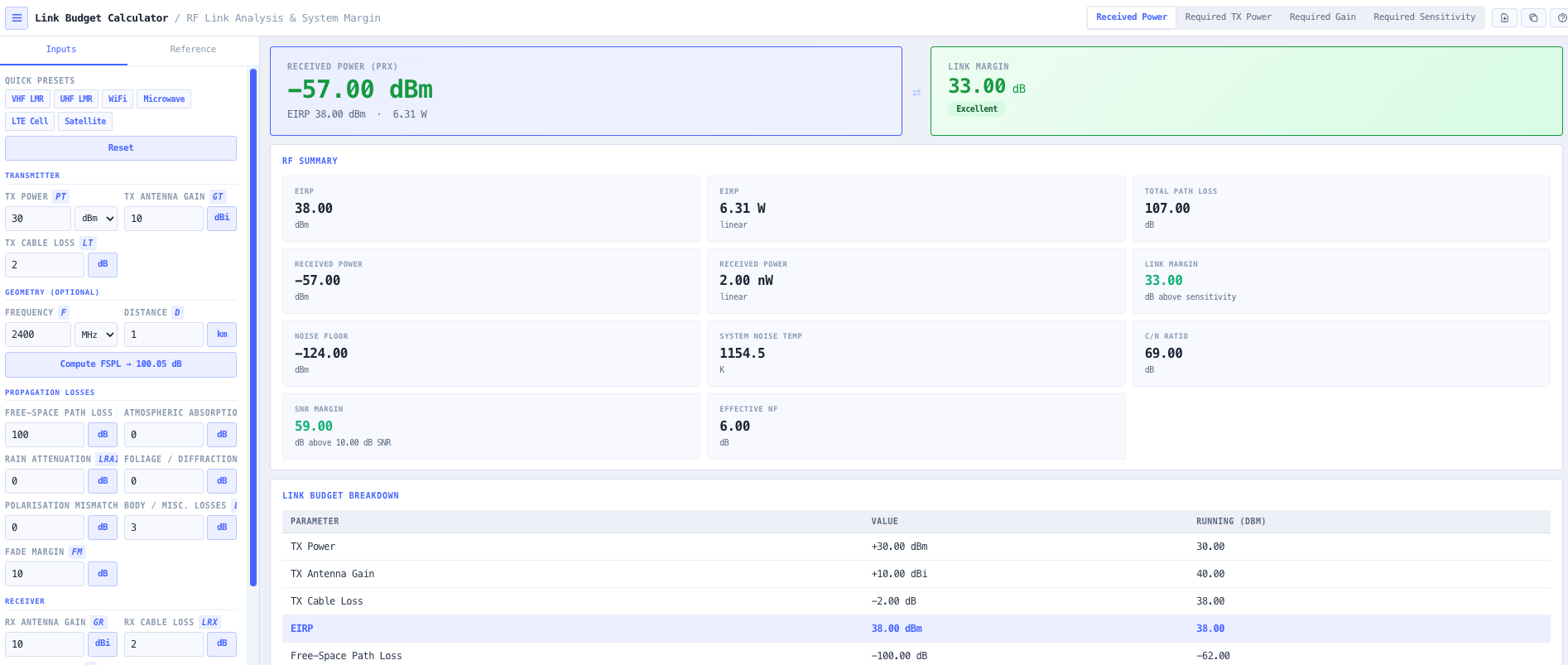
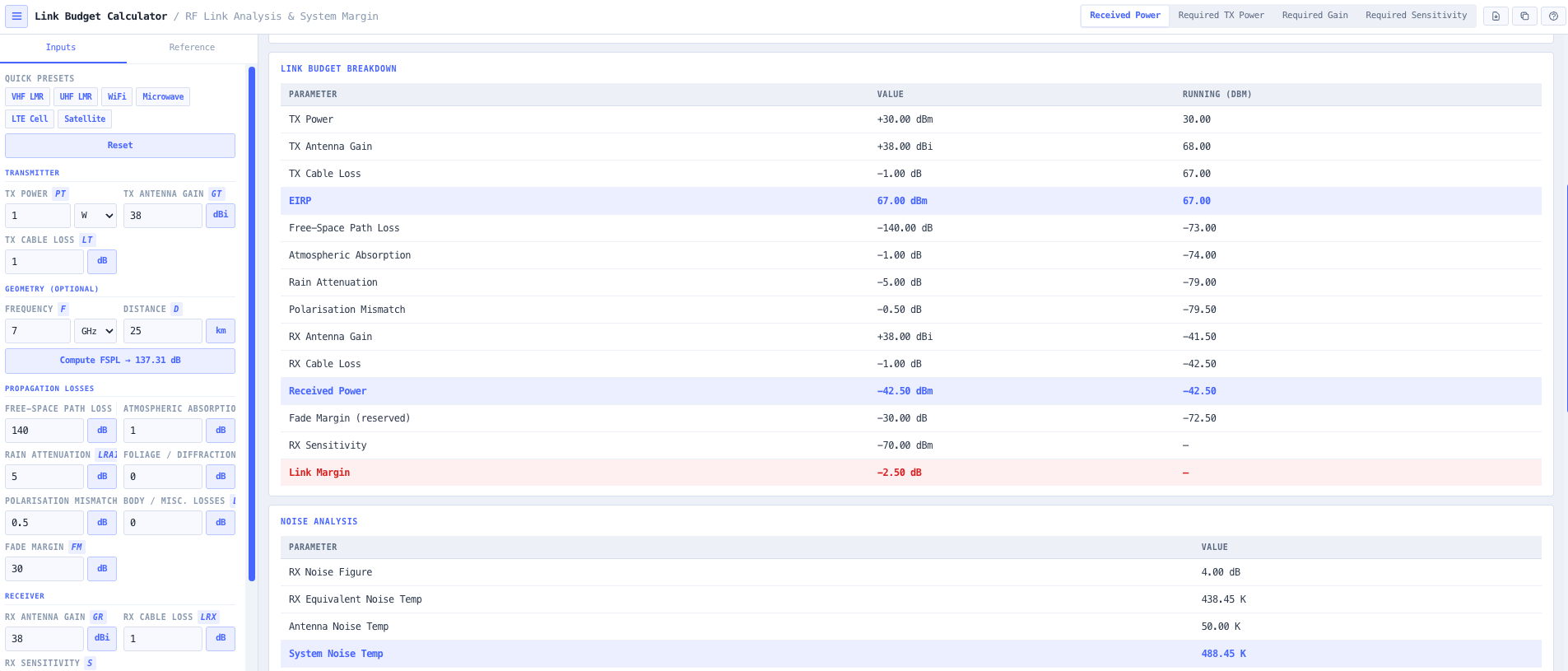
The noIM₃ Link Budget Calculator is the end to end workspace for that document. Transmitter parameters (output power, antenna gain, cable loss) feed an EIRP calculation. Propagation loss aggregates free space path loss, atmospheric absorption, rain, foliage and diffraction, and polarisation mismatch. Receiver parameters (antenna gain, cable loss, receiver sensitivity) close out the chain. Fade margin and link margin are reported explicitly so the operational availability is visible rather than implied. A full noise analysis covering receiver noise figure, system noise temperature, bandwidth, and antenna temperature returns noise floor in dBm and carrier to noise ratio in dB so signal quality is not just an afterthought to received power.

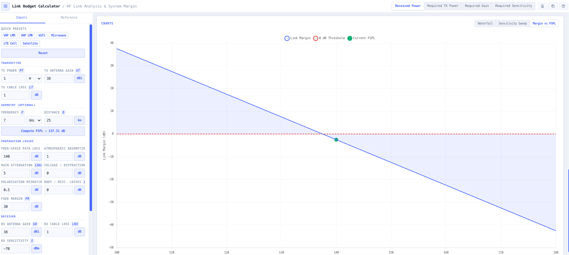
Built in presets cover VHF and UHF land mobile radio, WiFi 2.4 GHz and 5 GHz, LTE bands, satellite uplinks and downlinks, and microwave point to point backhaul. Each preset populates transmit power, antenna gain, cable loss, and receiver sensitivity for the common configuration so a usable answer is one click away. Manual entry is available throughout for unusual deployments, custom equipment, or cross checking against vendor proposed designs. Interactive waterfall and margin charts visualise how received power and link margin track with distance and frequency, supporting design discussions around antenna size, transmit power, frequency band selection, and reliability target.

Capabilities

Full transmitter and receiver chain

Configure transmitter output power in dBm or watts, transmit antenna gain in dBi, transmit feeder and connector loss, receive antenna gain, receive feeder and connector loss, and receiver sensitivity. The calculator aggregates these to compute EIRP at the transmitter, total system loss, and net received power at the receiver input.

Comprehensive propagation loss

Free space path loss to the standard ITU formulation. Atmospheric absorption from oxygen and water vapour. Rain attenuation against a configured rain rate. Foliage and diffraction losses. Polarisation mismatch loss between transmit and receive antennas. Each loss line is editable and surfaces in the budget breakdown so the contribution of each effect is visible rather than absorbed into a single propagation number.

Fade margin and link margin

Configurable fade margin reserved to absorb time varying propagation effects (multipath, rain, atmospheric variation). Link margin computed by comparing received power against receiver sensitivity after fade margin is applied. Explicit pass or fail against the target so underperforming links are flagged immediately.

Receiver noise analysis

Full receiver noise model. Receiver noise figure in dB. System noise temperature in Kelvin. Receiver bandwidth in Hz. Antenna noise temperature for satellite work where the look angle determines sky temperature contribution. Computes noise floor in dBm using the standard kTB plus noise figure relationship, and carrier to noise ratio in dB so signal quality is reported alongside received power.

EIRP calculation

EIRP equals transmit power plus transmit antenna gain minus transmit cable loss, surfaced in dBm and watts. Useful for confirming that the design respects the EIRP limit on the operating licence (ACMA, FCC, or international equivalent) before committing to the configuration.

Band presets

Quick select presets for VHF land mobile (148 to 174 MHz), UHF land mobile (400 to 470 MHz), WiFi 2.4 GHz, WiFi 5 GHz, LTE bands across the common Australian allocations, satellite uplinks and downlinks (C, X, Ku, Ka), and microwave backhaul (6, 7, 8, 11, 13, 15, 18, 23, 26, 28, 38 GHz). Each preset populates a sensible default for transmit power, antenna gain, cable loss, and receiver sensitivity so common scenarios reach a usable budget in one click.

Interactive waterfall and margin charts

Visualisations show received power versus distance, link margin versus distance, and sensitivity versus FSPL. Useful for understanding how rapidly margin is consumed by range, identifying the maximum operating distance against a sensitivity threshold, and producing visuals that support design discussions and customer reports.

Browser only computation

Runs entirely in your browser. No transmitter, antenna, or link parameter data is submitted to a server. Useful for commercially confidential infrastructure work, satellite ground segment, and environments where information security policy prohibits sending engineering data to third party services.

Standards & methodology

  • ITU R P.525. Calculation of free space attenuation
  • ITU R P.530. Propagation data and methods for terrestrial line of sight systems
  • ITU R P.676. Attenuation by atmospheric gases
  • ITU R P.838. Specific attenuation model for rain
  • ITU R P.840. Attenuation due to clouds and fog
  • ITU R P.341. The concept of transmission loss for radio links
  • ITU R P.372. Radio noise
  • ACMA radiocommunications licence conditions referencing antenna gain, EIRP, and receiver sensitivity

When to use this tool

  • Designing wireless point to point and point to multipoint links
  • Evaluating link margin for LTE, WiFi, and VHF and UHF land mobile systems
  • Satellite uplink and downlink budget planning
  • Microwave backhaul link planning across 6 to 38 GHz bands
  • RF propagation analysis with multi loss modelling
  • Assessing system performance under fade and noise conditions
  • Producing engineering documentation for ACMA radiocommunications licence applications
  • Validating that a vendor proposed link design meets target availability and link margin
  • Sizing antenna gain or transmit power against a required link margin
  • Producing carrier to noise ratio evidence for satellite link acceptance testing
  • Auditing an inherited link installation against current expected performance
  • Teaching link budget fundamentals and the contribution of each loss component

Is this the right tool for you?

Reach for the Link Budget Calculator in any of the following situations.

  • You are designing a microwave point to point backhaul link and need a complete link budget showing each propagation loss line and the resulting margin against the receiver sensitivity.
  • You are evaluating a satellite uplink or downlink and need full noise analysis (noise figure, system noise temperature, carrier to noise ratio) alongside received power.
  • You are planning an LTE fixed wireless access deployment and need to confirm link margin against rain rate, feeder loss, and antenna gain at the operating frequency.
  • You are designing a WiFi point to point link and need a defensible budget showing whether the link will close under realistic atmospheric and rain conditions, not just free space.
  • You are commissioning a VHF or UHF land mobile radio system and need to confirm coverage at the operating power level and antenna gain through the full link budget.
  • You are evaluating two candidate frequency bands or antenna sizes against the same link target and want a like for like budget comparison.
  • You are producing engineering documentation for an ACMA radiocommunications licence application and need a defensible link budget that the regulator can verify.
  • You are validating a vendor proposed link design and want an independent budget cross check before signing off the procurement.
  • You are sizing antenna gain or transmit power to meet a specified link margin and want a fast solver against the budget rather than iterating manually.
  • You are responsible for satellite link acceptance testing and need carrier to noise ratio evidence that meets the contractual target under the configured noise model.
  • You are auditing an inherited link installation against current expected performance and need a baseline budget to compare measured received power against.
  • You are training new RF engineers in link budget fundamentals and want a teaching tool that exposes each propagation loss line, fade margin, and the noise model separately.
  • You are evaluating whether a working link is failing because of propagation loss, noise floor, equipment degradation, or antenna VSWR, and need a budget you can pull each lever against.
  • You are producing customer ready engineering reports for backhaul or transport network rollouts and need waterfall budget breakdowns for each link in the network.
  • You are planning a temporary or event link and need a complete budget against rain rate and atmospheric conditions before committing equipment.
  • You are operating under a security regime that prohibits sending design data to third party services and need a link budget calculator that runs entirely in your browser.

Frequently asked questions

What does the link budget actually compute?

The classical link budget. Received power equals transmit power plus transmit antenna gain minus transmit cable loss minus total propagation loss plus receive antenna gain minus receive cable loss. Total propagation loss includes free space path loss, atmospheric absorption, rain attenuation, foliage and diffraction, and polarisation mismatch. Link margin equals received power minus receiver sensitivity minus fade margin. The calculator surfaces every line so the budget is auditable rather than a black box.

How is noise analysis handled?

Receiver noise floor follows the standard relationship. Noise floor in dBm equals minus 174 plus 10 log of bandwidth in Hz plus receiver noise figure in dB. For satellite work, antenna noise temperature is added through the system noise temperature calculation T equals Ta plus (1 minus 1 over Lc) times T0 plus T0 times (NF minus 1) divided by Lc. Carrier to noise ratio C over N is then received power minus noise floor. Useful for assessing whether the link is genuinely thermal limited or affected by external interference.

How is this different from the FSPL Calculator?

The FSPL Calculator focuses on free space path loss as a function of distance and frequency, with a basic link budget context. The Link Budget Calculator extends the analysis to a full operational budget including atmospheric absorption, rain, foliage, polarisation mismatch, fade margin, and full noise analysis with carrier to noise ratio. Use FSPL when you only need the free space loss number. Use the Link Budget Calculator for the full operational budget that goes into a design package.

How is this different from the Friis Transmission Calculator?

Friis is the free space received power equation in its simplest form (Pr equals Pt plus Gt plus Gr minus FSPL). The Link Budget Calculator extends that with feeder loss, atmospheric and rain attenuation, foliage, polarisation, fade margin, and receiver noise analysis. Use Friis for fast feasibility and teaching. Use the Link Budget Calculator for an operational budget you can hand to a regulator or customer.

How is this different from the noIM₃ Link Planner?

The Link Budget Calculator is a single point analysis at a configured distance and frequency, with manual entry for each propagation loss line. The noIM₃ Link Planner is a full ITU anchored RF planning workstation with terrain accurate path profiles from Mapbox global Terrain RGB DEM, automatic ITU model coverage (P.526, P.530, P.676, P.838, P.840, P.2108), Fresnel zone clearance against terrain, and full provenance for every input. Use the Link Budget Calculator for fast point analysis. Use the Link Planner for full microwave link design with terrain.

What fade margin should I use?

Fade margin depends on frequency, path length, climate, and the required availability target. For short range terrestrial links at low frequency, 10 to 20 dB is typical. For microwave backhaul at 6 to 11 GHz, 30 to 40 dB is typical. For 18 to 38 GHz millimetre wave, 35 to 45 dB or more is required to meet typical 99.99 per cent availability targets. The exact value comes out of an ITU P.530 multipath and rain calculation, which the noIM₃ Link Planner handles end to end. The Link Budget Calculator accepts the fade margin as a configurable input so you can plug in the value from the appropriate analysis.

Can I solve for distance or required EIRP?

Yes. The visualisations show received power and link margin versus distance, so you can read off the maximum distance at which the link still meets target margin. For required EIRP, fix the receiver sensitivity, link margin, propagation losses, and receive side gain, then iterate on transmit power and transmit antenna gain to find the EIRP that closes the budget.

Does any data leave my browser?

No. The calculator runs entirely in your browser. No transmitter, antenna, or link parameter data is submitted to a server. Useful for commercially confidential infrastructure work, satellite ground segment, and environments where information security policy prohibits sending engineering data to third party services.