Microwave Link Planning

Free Space Path Loss Calculator

Free space path loss in dB across distance, frequency, and antenna gain. Solve for FSPL, distance, or frequency, with full link budget, fade margin, Fresnel zone clearance, and presets for WiFi, LTE, 5G NR, VHF, UHF, ISM, and microwave bands.

Overview

Free space path loss is the foundation propagation loss every RF link plan starts from. It quantifies the attenuation a signal experiences travelling between two isotropic antennas in vacuum, governed by the inverse square spreading of the wavefront and a frequency dependent term that captures how higher frequency wavefronts couple less effectively into a fixed receive aperture. Every additional propagation effect (rain, gas, diffraction, multipath, clutter) is layered on top of FSPL. Get the FSPL number wrong and the rest of the budget is wrong by the same amount.

The noIM₃ Free Space Path Loss Calculator computes FSPL using the standard logarithmic form. FSPL in dB equals 20 log of distance plus 20 log of frequency plus a constant. For distance in km and frequency in MHz the constant is 32.45. For distance in km and frequency in GHz it is 92.45. For distance in metres and frequency in MHz it is minus 27.55. The calculator handles all unit families and surfaces the FSPL number directly. A bidirectional solver inverts the relationship so you can solve for the maximum distance achievable at a given FSPL budget, or for the required frequency to meet a distance and FSPL constraint.

Beyond the FSPL itself, the workspace covers the full link picture. Antenna gain compensation at both ends gives EIRP and received power. System loss and fade margin reduce the link margin against a configured receiver sensitivity. First Fresnel zone radius and percentage clearance support line of sight analysis for terrestrial microwave, fixed wireless access, and point to point work where terrain and obstacles intrude into the radiation envelope. Built in presets cover WiFi 2.4 GHz and 5 GHz, LTE, 5G NR, VHF, UHF, ISM 915 MHz, and microwave backhaul bands, so common feasibility questions are one click away.

Capabilities

FSPL computation across distance and frequency

Standard logarithmic formula implemented across all unit families. FSPL in dB equals 20 log of distance plus 20 log of frequency plus a unit dependent constant (32.45 for km and MHz, 92.45 for km and GHz, minus 27.55 for metres and MHz, and so on). All unit conversions are handled automatically and the constant is selected to match the input units.

Bidirectional solver

Solve for FSPL given distance and frequency, or invert the relationship to solve for maximum achievable distance at a given FSPL budget, or for the required frequency to meet a distance and FSPL constraint. Useful for the early sizing question of how far a link can reach against a target loss, or which frequency band can deliver a required reach within an allowed budget.

Antenna gain compensation and EIRP

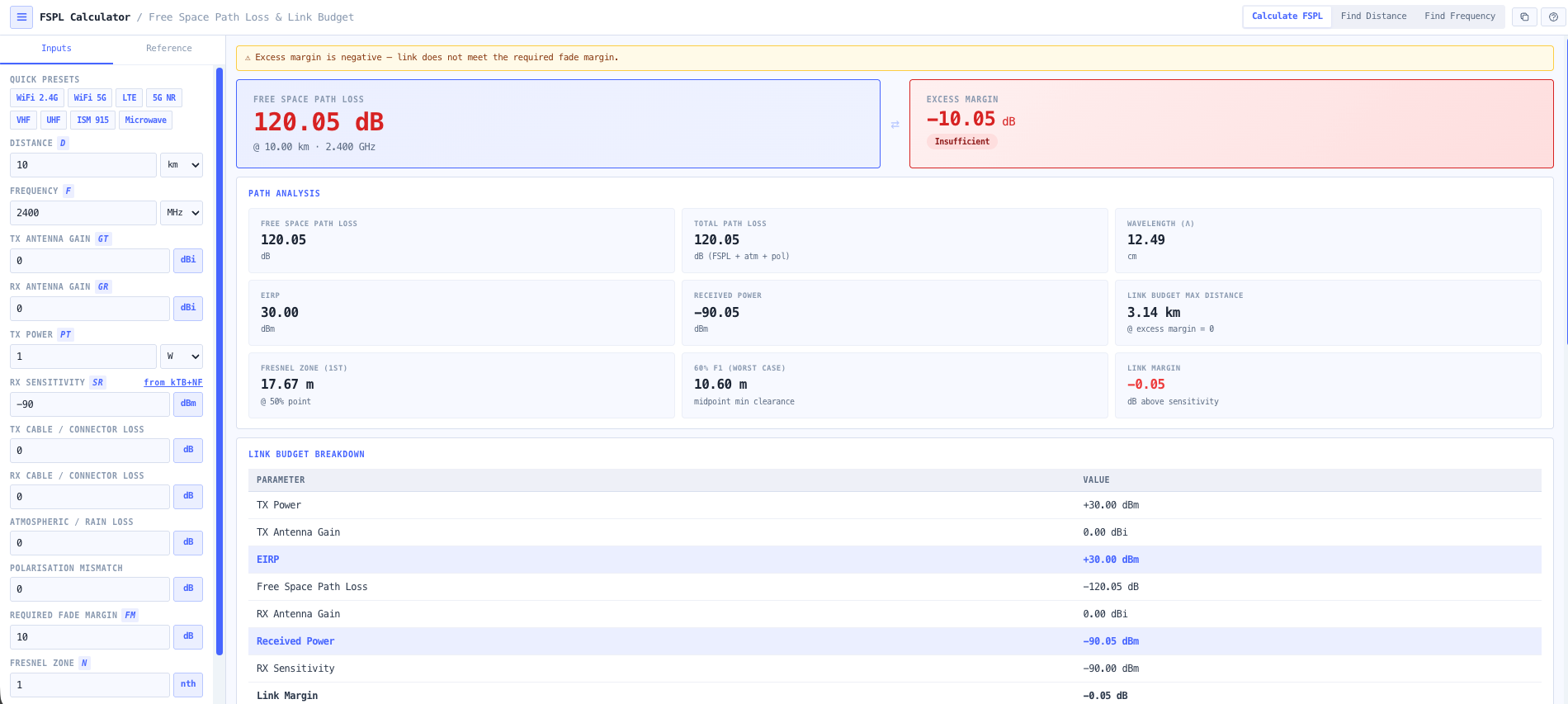
Transmit and receive antenna gains in dBi feed directly into the link budget. EIRP equals transmit power plus transmit antenna gain. Received power equals EIRP minus FSPL plus receive antenna gain minus system losses. All quantities surfaced together so the link budget is an obvious read down rather than a multi step calculation.

Full link budget breakdown

Shows transmit power, transmit antenna gain, FSPL, receive antenna gain, system losses, fade margin, received power, configured receiver sensitivity, and resulting link margin in dB. Identifies underperforming links and supports the design discussion around antenna size, transmit power, and frequency band selection.

Fade margin analysis

Configurable fade margin is subtracted from the link margin so the budget reflects realistic operational availability rather than only the static free space case. Useful for terrestrial microwave links where multipath and rain require an explicit margin allocation, and for fixed wireless access where seasonal or weather driven fading needs to be planned for.

Fresnel zone clearance

Computes first Fresnel zone radius at any point along the path from frequency and distance. Returns percentage clearance against a configured obstacle height, supporting line of sight analysis for terrestrial microwave and point to point links. Useful for confirming whether a candidate path needs antenna height adjustment, terrain clearance work, or alternative routing.

Band presets

Built in presets for WiFi 2.4 GHz, WiFi 5 GHz, LTE bands, 5G NR sub 6 GHz, VHF, UHF, ISM 915 MHz, and microwave backhaul bands. Each preset populates frequency, typical transmit power, antenna gain, and receiver sensitivity for the common configuration so a usable answer is one click away. Manual entry remains available for unusual band selections, amateur radio, or millimetre wave deployments.

Interactive visualisation

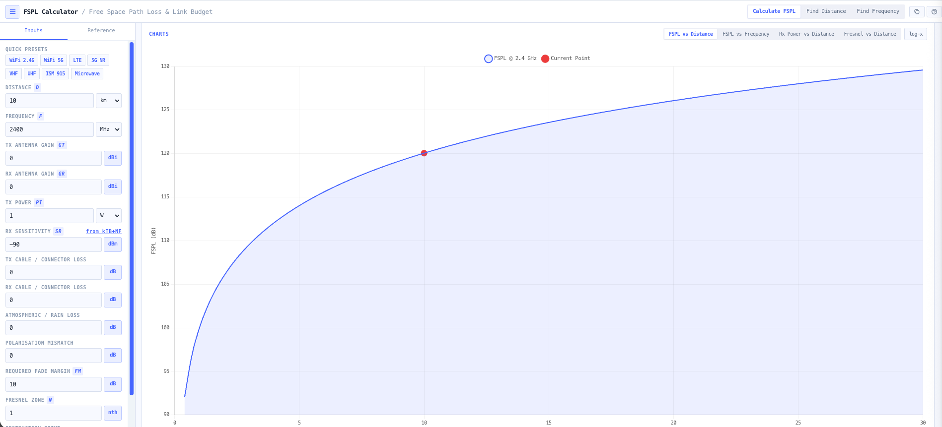
Charts show FSPL versus distance, FSPL versus frequency, and received power versus distance. Useful for understanding the rate at which margin is consumed by range, identifying the maximum operating distance against a receive sensitivity threshold, and producing visuals that explain link feasibility to non specialist stakeholders.

Browser only computation

Runs entirely in your browser. No frequency, distance, antenna, or transmit power data is submitted to a server. Useful for commercially confidential infrastructure work and environments where information security policy prohibits sending engineering data to third party services.

Standards & methodology

  • ITU R P.525. Calculation of free space attenuation
  • ITU R P.341. The concept of transmission loss for radio links
  • IEEE 145. Standard definitions of terms for antennas
  • Friis transmission equation (Friis 1946) underlying free space propagation
  • ACMA radiocommunications licence conditions referencing antenna gain and EIRP

When to use this tool

  • Planning WiFi, LTE, and 5G NR point to point links
  • Microwave backhaul and satellite free space link assessment
  • Line of sight evaluation with Fresnel zone clearance
  • Estimating received power and fade margins for system reliability
  • Link budget validation for VHF, UHF, ISM, and microwave bands
  • Educational demonstration of FSPL and distance and frequency scaling
  • Comparing two candidate frequency bands for the same path
  • Solving for maximum link distance against a configured receive sensitivity
  • Producing FSPL evidence for ACMA radiocommunications licence applications
  • Sanity checking vendor proposed link budgets against the underlying physics
  • Evaluating fixed wireless access deployments in regional and remote areas
  • Producing teaching materials and reference calculations for RF engineering courses

Is this the right tool for you?

Reach for the Free Space Path Loss Calculator in any of the following situations.

  • You are planning a WiFi point to point link between two buildings and need a fast FSPL number to size the antenna and transmit power.
  • You are sizing an LTE or 5G NR fixed wireless access deployment and need received power versus range so you can plan cell or terminal placement against the receive sensitivity.
  • You are designing a microwave backhaul link and want a free space upper bound on the FSPL before adding rain, gas, and diffraction losses to the budget.
  • You are evaluating a satellite free space link and need the FSPL component of the budget separately from atmospheric and pointing losses.
  • You are conducting a line of sight survey for a terrestrial microwave path and need first Fresnel zone radius and clearance against tower or terrain heights along the path.
  • You are solving for the maximum distance achievable for a given transmit power, antenna gain, and receive sensitivity against an FSPL only budget.
  • You are comparing two candidate frequency bands (for example 2.4 GHz versus 5 GHz, 900 MHz versus 5.8 GHz) for the same path to see which delivers better margin for the same antenna and transmit power.
  • You are producing the propagation section of an ACMA radiocommunications licence application and need defensible FSPL output that the regulator can verify.
  • You are sanity checking a vendor proposed link budget against the underlying free space physics before signing off the procurement.
  • You are evaluating fixed wireless access for a regional or remote Australian deployment and need received power against range estimates to plan tower siting.
  • You are training new RF engineers in the inverse square law and the dB form of FSPL and want a teaching tool that surfaces the formulas alongside the result.
  • You are running early stage feasibility for a 5G NR mmWave deployment and need to see how rapidly FSPL scales with frequency at small cell distances.
  • You are responsible for an ISM 915 MHz LoRa deployment and need range estimates against a 137 dBm or better receiver sensitivity threshold.
  • You are evaluating whether to use a higher gain antenna or a lower frequency band to extend the reach of an existing link.
  • You are designing a temporary or event link and need a fast FSPL feasibility check before specifying equipment.
  • You are operating under a security regime that prohibits sending design data to third party services and need an FSPL calculator that runs entirely in your browser.

Frequently asked questions

What formula does the calculator use?

FSPL in dB equals 20 log of distance plus 20 log of frequency plus a unit dependent constant. For distance in km and frequency in MHz the constant is 32.45. For distance in km and frequency in GHz it is 92.45. For distance in metres and frequency in MHz it is minus 27.55. For distance in metres and frequency in GHz it is 32.45 (with appropriate unit handling). The calculator selects the constant automatically based on the input unit families so you do not need to keep the conversion in your head.

When does free space path loss actually apply?

FSPL assumes ideal line of sight conditions with no obstructions, no terrain, no atmospheric absorption, no multipath, and that both ends of the link are in the far field of each antenna. It is the right model for satellite links above the atmosphere, for short range line of sight links, and as the upper bound starting point for any link budget. For terrestrial links over significant range, you also need rain attenuation (P.530, P.838), atmospheric gas absorption (P.676), and diffraction over terrain (P.526), which the noIM₃ Link Planner handles to ITU P.530.

How is this different from the Friis Transmission Calculator?

The FSPL Calculator focuses on the propagation loss in dB as a function of distance and frequency, plus the surrounding link budget context. The Friis Transmission Calculator works the same equation in its complete received power form (Pr equals Pt plus Gt plus Gr minus FSPL) with simpler inputs. Use FSPL when you want the loss number and full link budget breakdown including fade margin and Fresnel clearance. Use Friis when you want a quick free space received power and signal strength classification.

How is this different from the Link Budget Calculator?

FSPL is the free space upper bound and is one input into a full link budget. The Link Budget Calculator extends the analysis to include feeder losses, miscellaneous losses, fade margin, atmospheric and rain attenuation, and link availability against a target. Use FSPL when you only need the propagation loss and basic link margin. Use the Link Budget Calculator for the full operational budget that goes into a design package.

How is the Fresnel zone radius calculated?

First Fresnel zone radius F1 in metres equals 17.32 times square root of (d1 times d2 over (d times f in GHz)), where d1 and d2 are the distances from each end to the obstacle in km, and d is the total path length in km. For midpoint clearance, this simplifies to 8.66 times square root of (d divided by f in GHz). Output includes the radius and the percentage clearance against a configured obstacle height for line of sight assessment.

What does fade margin do in the budget?

Fade margin is the headroom in the link budget reserved to absorb time varying propagation effects (multipath fading, rain, atmospheric variation) without dropping below the receiver sensitivity threshold. The calculator subtracts the configured fade margin from the link margin output so the reported number reflects realistic operational availability rather than only the static free space case. Typical microwave designs use 20 to 40 dB fade margin depending on frequency and availability target.

Does any data leave my browser?

No. The calculator runs entirely in your browser. No frequency, distance, antenna gain, or transmit power data is submitted to a server. Useful for commercially confidential infrastructure work and environments where information security policy prohibits sending engineering data to third party services.

Can I solve for distance or frequency rather than FSPL?

Yes. The bidirectional solver inverts the relationship so you can input an FSPL budget plus distance to solve for the required frequency, or input an FSPL budget plus frequency to solve for the maximum achievable distance. Useful for early sizing questions where the question is reversed (how far can I reach, or what frequency do I need) rather than what is the loss.