Visual network design canvas
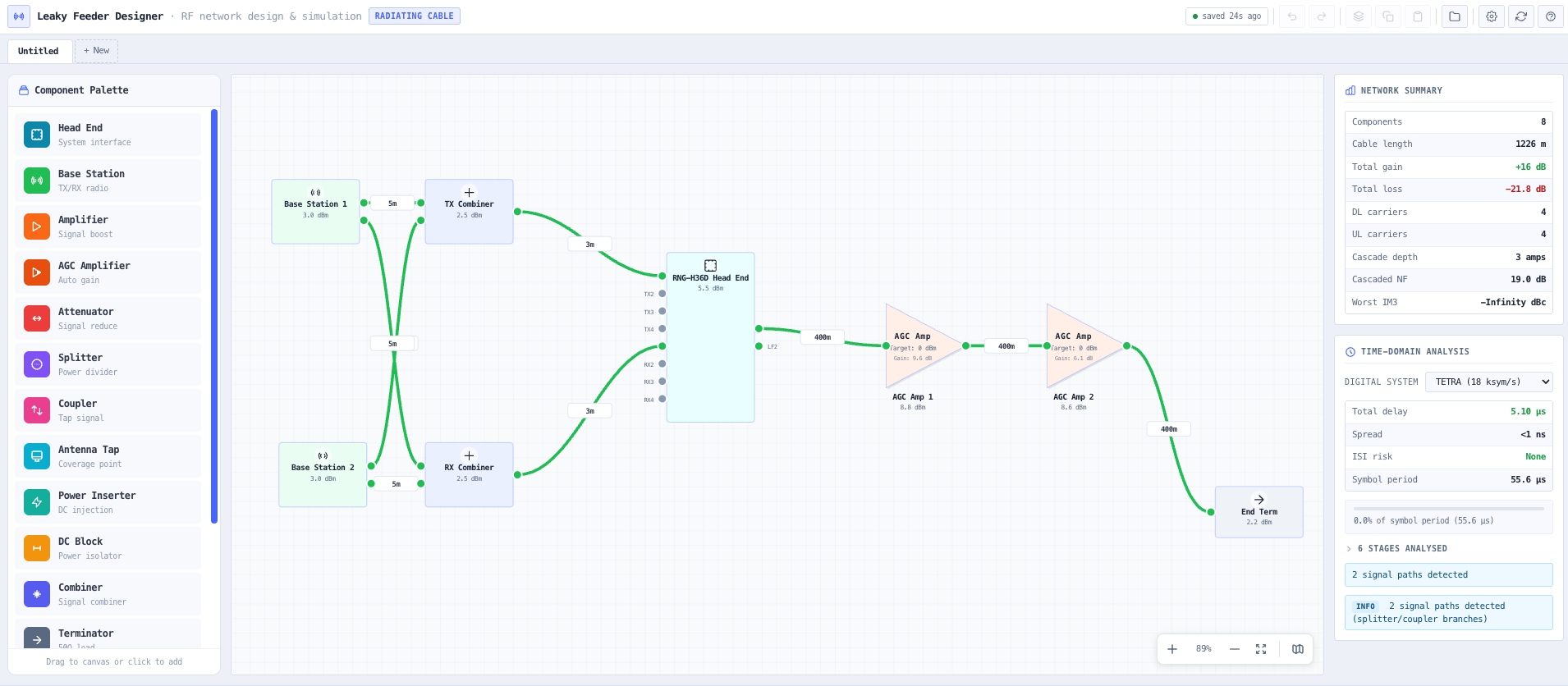
Drag and drop radiating cable, line amplifiers, AGC amplifiers, attenuators, splitters, hybrid combiners, directional couplers, antenna taps, power inserters, DC blocks, terminations, base stations, head ends, donor antennas, test points, and mobile radios onto a canvas representing the tunnel, mine, or building. Every component carries its full electrical specification so the diagram is the input to the simulation rather than an afterthought. Connection validation enforces output to input on wired connections and a single antenna port on mobile radios that draws an over-the-air dashed link to any other component. Undo and redo, copy and paste, right-click context menus, and a context-aware properties panel cover design productivity.
Multi-carrier RF propagation engine
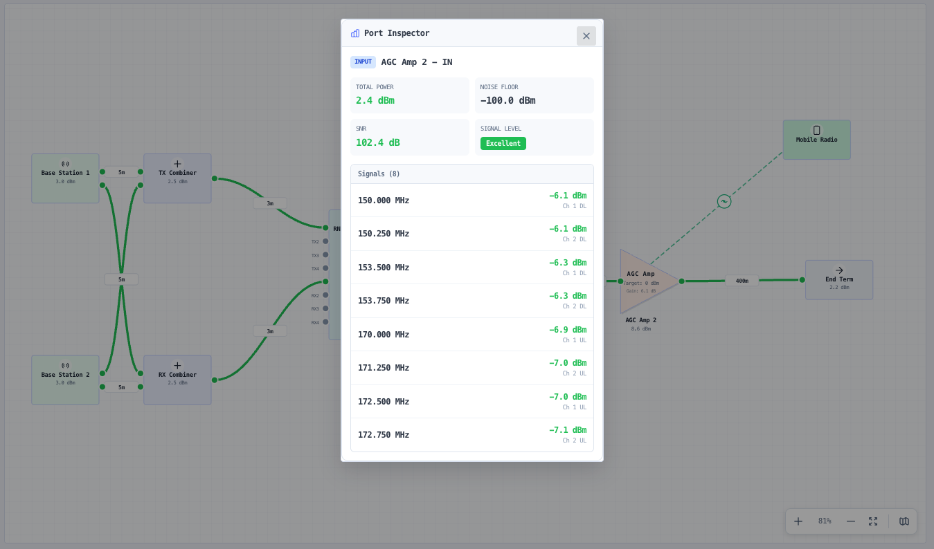
The Network Simulation Engine walks the network graph from each signal source through every wired component, accumulating cable loss (fitted to manufacturer datasheets), splitter and combiner insertion loss, amplifier gain, and AGC target-power regulation. Per-tone power is tracked at every port — a four-carrier bidirectional setup propagates eight tones (four downlink and four uplink) through the whole chain. The Port Inspector shows the composite power, noise floor, SNR, and the full per-tone breakdown at any selected port. The Enhanced Simulation Engine adds Friis-cascaded noise figure with inter-stage cable loss explicitly inserted (so the second amplifier in a chain is not credited with the first amplifier’s gain when the cable in between has erased it).
Intermodulation with duplexer / passband filtering
Computes two-tone (2a−b) and three-tone (a+b−c) IM3 products across the amplifier chain using vendor specific OIP3 and Rapp-soft compression. Each amplifier, AGC amplifier, and head end carries optional downlink and uplink passband ranges. When set, IM products falling outside both passbands are dropped from the analysis — the duplexer or cavity filter on the real device cannot pass them. The result is honest in-band IM3 that does not include 50 MHz mixer products contributing to a 150 MHz channel. The per-amp spectrum analyser modal shows the full IM product list, sortable by power or frequency, and the worst-case dBc figure that survives the passband filter.
DC power feed solver
Tracks the DC power feed across the cable run and amplifier chain. Solves voltage drop along the cable using the manufacturer DC resistance per 100 metres and the per-amp current draw. Identifies the headroom against the amplifier minimum supply voltage at each node. Useful for sizing where remote-powering by the head end reaches its limit and where additional power inserters are required.
Bidirectional analysis: uplink and downlink
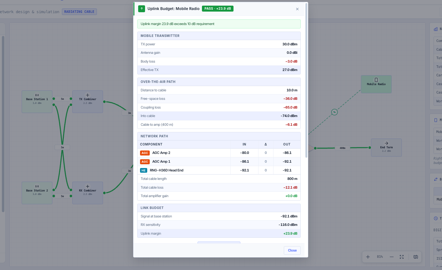
The downlink (base to mobile) and uplink (mobile to base) are simulated separately. Every port renders a colour-coded composite-power label on the canvas against the configured target threshold, and the Port Inspector gives the full per-tone breakdown, noise floor, and SNR at any point along the run. The Uplink Budget Panel runs the reverse path for any selected mobile radio: mobile TX power minus body loss plus antenna gain, over-the-air free-space loss, coupling loss into the radiating cable, then back through the amplifier cascade to the base receiver. A pass / marginal / fail status is computed against the configured RX sensitivity. The Bidirectional Links summary table flags mobiles that pass on one direction but fail on the other and shows the limiting direction.
Over-the-air mobile radio coverage
Mobile radios sit on the canvas with a single ANT antenna port. Drag the wire from the ANT port onto any port on an amplifier, cable, splitter, or terminator and the radio is OTA-linked to that component (no real cable is created — the visual is a dashed antenna line). Validation enforces that the mobile sits exactly on an enabled carrier’s centre frequency (mobile TX equals the carrier downlink, mobile RX equals the carrier uplink) and that the mobile’s system type (TETRA, P25, DMR, Analogue FM, or custom) matches the carrier’s system. Distance to the radiating cable, antenna gain, and body loss are first-class parameters in the OTA budget.
Off-air donor (repeater) link analysis
For repeater designs where the head end does not carry its own carriers but picks them up off-air from a parent macro cell, drop a donor antenna onto the canvas. The Donor Links table computes the donor signal level at the indoor-unit input (donor EIRP, free-space path loss to the donor, antenna gain, and feeder loss) and the system isolation margin — the gap between the network forward gain and the donor antenna isolation back into the radiating cable. Each donor is flagged OK, marginal, or unstable, because if the forward gain exceeds the isolation the loop oscillates. It catches the two failure modes of an off-air repeater (donor too weak, or isolation too tight) before commissioning.
Per-port spectrum analyser and uplink budget modals
Right-click any amplifier or head end and open the spectrum analyser modal: input and output power per tone, cascaded NF and OIP3, worst-case IM3 (after passband filtering), P1dB headroom, IM product list, cascade info, and DC power status. Right-click any mobile radio and open the uplink budget modal: mobile TX parameters, over-the-air path, full path through the network, link budget summary with the margin against RX sensitivity, and the downlink equivalent.
Validation and live warnings
A live validation panel surfaces orphaned components, cycles in the graph, unterminated cable ends (radiating cables exempted, head-end LF outputs exempted since the chassis terminates them internally), cable operating-band exceedances against the manufacturer datasheet range, mobile radio frequency or system-type mismatches against the network carriers, and AGC headroom advisories. Each warning is severity-tinted (error, warning, info) and click-locates the responsible component on the canvas.
Vendor cable database fitted to manufacturer datasheets
Radiating: RFS RADIAFLEX RCF12 (½″), RCF78 (⅞″), RCF78-MSHA, RLF114 (1¼″ PE jacket), RLKW114 (1¼″ rail-tunnel grade); CommScope RADIAX RXL-12-CL, RXL-78-CL, RXL-114-CL. Non-radiating: Times Microwave LMR-100A, LMR-195, LMR-240, LMR-400, LMR-600, LMR-900; Belden RG-213/U. Every cable carries longitudinal-loss coefficients (K₁ and K₂) least-squares refit to the manufacturer datasheet table — fit RMS error under 0.1 dB/100m across the operating band for the radiating and LMR cables (PE-dielectric RG-213 fits the √f model less cleanly at the band edges) — plus impedance, max frequency, max power, loop DC resistance taken from the datasheet, outer diameter, minimum bend radius, weight, velocity factor, temperature range, and fire-rating notes.
Autosave across sessions
The in-progress design is automatically saved to browser localStorage on every change. A tab refresh or accidental close restores the network exactly where the user left it. The Reset (↻) control in the toolbar clears the autosave and rebuilds the default demo topology — the explicit escape hatch back to defaults.