Cable Utilities

PIM Calculator

Passive Intermodulation analysis for cellular and RF systems aligned with IEC 62037. Calculate 3rd, 5th, 7th, and 9th order products, detect receive band hits, and estimate system level PIM from component ratings.

Overview

Passive intermodulation, or PIM, is the silent killer of cellular and high power RF systems. Two strong transmit carriers passing through a passive component (a connector, a jumper, an antenna, a duplexer, a filter) generate intermodulation products at predictable sum and difference frequencies. Most of those products are out of band and harmless, but a poorly mated connector, an oxidised joint, or a low quality component can drop a 3rd order product directly into the receive band, raising the noise floor across the entire sector and pushing carrier to noise ratio below threshold for users at cell edge. Cellular operators report PIM as one of the most common causes of unexplained capacity loss on otherwise healthy sites.

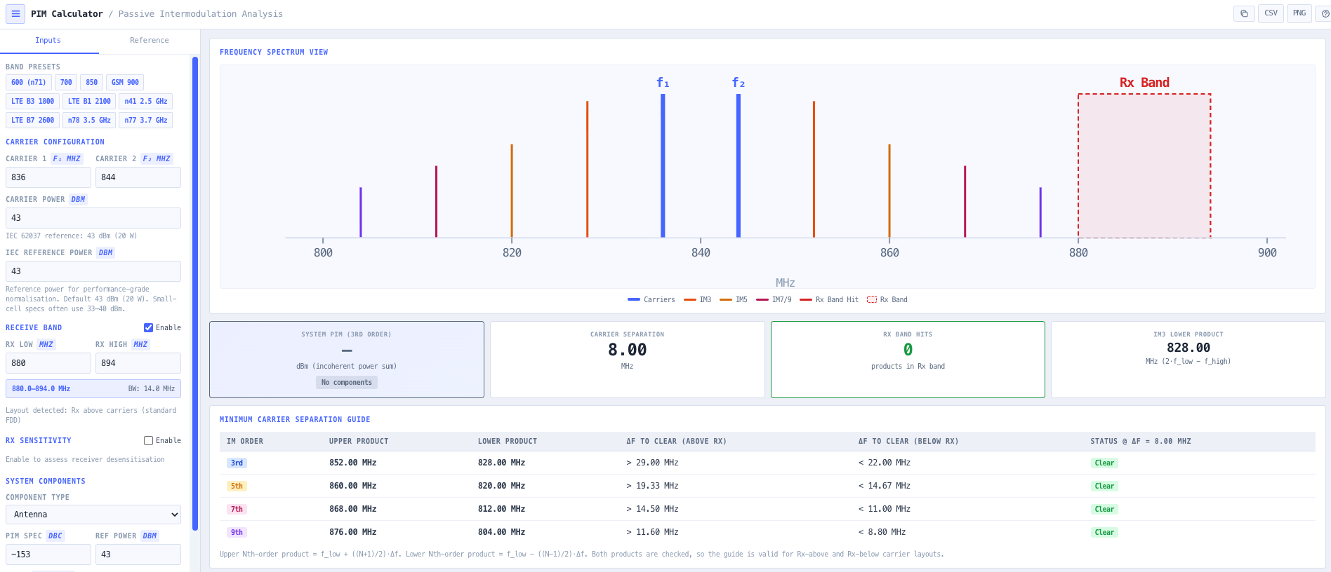
The noIM₃ PIM Calculator is a precision RF utility for diagnosing, designing, and validating against passive intermodulation. It computes 3rd, 5th, 7th, and 9th order intermodulation products from a dual carrier configuration using standard frequency relationships (2 f1 minus f2 for IM3, 3 f1 minus 2 f2 for IM5, and so on). Carrier separation guidance shows the minimum delta f required to keep each product order out of a target receive band. Receive band edges can be configured directly so the calculator automatically flags any in band hits and surfaces the desensitisation risk.

System level PIM is estimated by aggregating per component PIM ratings (in dBc referenced to the IEC 62037 dual tone 43 dBm test condition). The lowest rated component in the RF path drives the worst case system PIM, so the calculator identifies the limiting component and supports component selection trade offs against capital cost. Built around IEC 62037 measurement principles, the tool supports base station design, tower top component validation, frequency plan optimisation, and the troubleshooting workflow when a working sector starts losing capacity for no obvious reason.

Capabilities

Multi order intermodulation analysis

Computes 3rd, 5th, 7th, and 9th order intermodulation products using standard frequency relationships such as 2 f1 minus f2 for IM3 and 3 f1 minus 2 f2 for IM5. IEC 62037 formally specifies 3rd order testing, but higher orders are surfaced for engineering awareness and frequency planning insight, especially in dense multi band sites.

IEC 62037 reference mode

Implements the industry standard 43 dBm (2 by 20 watt) dual tone test condition consistent with IEC 62037. Component PIM specifications expressed as dBc referenced to that condition can be aggregated to estimate worst case system PIM performance at the actual operating power level.

Receive band interference detection

Configure receive band edges directly. The calculator automatically flags any intermodulation product that lands inside the receive band. Highlighted products surface the desensitisation risk by comparing calculated intermodulation level against receiver sensitivity, so the design discussion can move from theoretical to actual impact on the user.

Carrier separation guidance

Returns the minimum carrier spacing (delta f) needed to keep each intermodulation order clear of a target receive band. Useful for frequency planning teams choosing between multiple candidate carrier pairs, and for site engineers diagnosing a marginal pair that just clips the receive band edge.

System component aggregation

Add multiple passive components (antennas, connectors, jumpers, filters, duplexers) with individual PIM ratings in dBc. The calculator determines worst case system IM3 from the lowest rated component in the RF path, identifying the bottleneck and supporting component selection trade offs.

Spectrum visualisation

Interactive spectrum view shows the two carriers, the 3rd, 5th, 7th, and 9th order intermodulation products, and the configured receive band overlay. Direct hits on the receive band are highlighted, making the problem and the candidate fix immediately obvious to a non specialist stakeholder.

Receiver sensitivity check

Compare estimated intermodulation level against the receiver sensitivity threshold, returning a desensitisation margin in dB. Useful for justifying a tower top inspection or a connector retorque against the actual capacity impact rather than a theoretical risk.

Browser only computation

Runs entirely in your browser. No carrier frequencies, component data, or design content is submitted to a server. Useful for commercially confidential cellular and RF infrastructure work, or any environment where information security policy prohibits sending engineering data to third party services.

Standards & methodology

  • IEC 62037. Passive RF and microwave devices, intermodulation level measurement
  • ETSI TS 134 121. Cellular receiver sensitivity reference
  • 3GPP TS 36.104. Base station radio transmission and reception (LTE)
  • ACMA technical limits for cellular site compliance

When to use this tool

  • Cellular base station PIM analysis across 700, 850, 900, 1800, 2100, and 2600 MHz bands
  • LTE and 5G multi carrier frequency planning at high site densities
  • Tower top amplifier and antenna validation against PIM specifications
  • Evaluating connector, jumper, and filter PIM ratings before procurement
  • Troubleshooting receiver desensitisation and unexplained sector capacity loss
  • Validating that a candidate carrier pair will not generate in band intermodulation
  • Producing PIM analysis evidence for ACMA cellular site compliance
  • Justifying a tower top inspection or component replacement against measured impact
  • Comparing component selection trade offs against capital cost on greenfield builds
  • Auditing an inherited cellular site against current PIM rating standards
  • Training new RF engineers in passive intermodulation theory and mitigation
  • Supporting carrier addition planning where the new carrier risks creating PIM hits

Is this the right tool for you?

Reach for the PIM Calculator in any of the following situations.

  • You are responsible for a cellular sector that has lost capacity for no obvious reason and want to confirm whether passive intermodulation is the cause before sending a crew up the tower.
  • You are designing a multi carrier base station and need to confirm that the proposed carrier pair will not generate intermodulation products that fall inside the receive band.
  • You are validating tower top amplifier and antenna specifications against an IEC 62037 PIM rating before signing off the site design.
  • You are choosing between connectors, jumpers, or filters for a high power RF path and want to identify which component will be the system level PIM bottleneck.
  • You are diagnosing intermittent receiver desensitisation on a cellular site that has been operating cleanly for months.
  • You are planning to add a new carrier to an existing cellular sector and want to confirm the addition will not create in band intermodulation hits on the existing receive bands.
  • You are producing PIM analysis evidence for an ACMA cellular site compliance submission or internal engineering audit.
  • You are responding to a customer report of poor cell edge performance and need to quantify the desensitisation margin against receiver sensitivity.
  • You are auditing an inherited cellular site against current PIM rating standards and need a documented analysis of where the design margin currently sits.
  • You are comparing two candidate carrier pairs and want to know which one needs the smaller delta f to keep intermodulation products clear of the receive band.
  • You are training new RF engineers in passive intermodulation theory and want a teaching tool that surfaces the relationship between dual carrier inputs and intermodulation outputs visually.
  • You are responsible for a frequency planning team rolling out new spectrum and need a fast PIM check across multiple candidate carrier pairs.
  • You are operating under a security regime that prohibits sending design data to third party services and need a calculator that runs entirely in your browser.
  • You are sanity checking a vendor proposed component selection against the IEC 62037 reference and want an independent PIM analysis before accepting the bill of materials.
  • You are responsible for a tower top engineering inspection program and need a way to prioritise which sites are most likely suffering from PIM degradation.

Frequently asked questions

What is passive intermodulation and why does it matter?

Passive intermodulation (PIM) is intermodulation generated in passive components (connectors, jumpers, antennas, duplexers, filters) when two strong transmit carriers pass through a non linearity such as a poor metal to metal contact, oxidation, or magnetic material. The resulting products land at predictable sum and difference frequencies. When one of those products falls inside the receive band, the noise floor rises and receiver sensitivity drops, sometimes by 10 dB or more, which directly costs cell edge coverage and capacity.

What is IEC 62037?

IEC 62037 is the international standard for measuring passive intermodulation in RF and microwave devices. It specifies a dual tone test condition (typically 2 by 20 watt at 43 dBm per tone) with the 3rd order product measured against the carriers in dBc. Component datasheets that quote PIM in dBc are referenced to this test condition. The calculator implements the same reference so component ratings can be applied directly.

How is system level PIM estimated?

System level PIM is dominated by the lowest rated component in the RF path. The calculator aggregates per component PIM ratings, identifies the limiting component, and reports worst case system IM3 at the actual operating power level. This focuses procurement and remediation effort on the component that actually drives the system performance rather than spreading effort across all components in the path.

Which intermodulation orders are calculated?

3rd, 5th, 7th, and 9th order intermodulation products. IEC 62037 formally specifies 3rd order testing because IM3 has the largest amplitude and lands closest to the carriers. Higher orders are surfaced for engineering awareness, especially in dense multi band sites where IM5 or IM7 can become the dominant problem when IM3 has been engineered out.

How does receive band hit detection work?

Configure the receive band edges in MHz directly. The calculator computes every IM3, IM5, IM7, and IM9 product frequency from the carrier inputs, then flags any product that falls between the configured band edges. Flagged products are highlighted on the spectrum view and the desensitisation margin against receiver sensitivity is reported in dB.

What is carrier separation guidance?

For each intermodulation order, the calculator returns the minimum delta f between the two carriers needed to keep that order clear of the configured receive band. Useful for frequency planning teams choosing between candidate pairs, and for site engineers diagnosing a marginal pair that just clips the receive band edge.

How is this different from the Intermodulation Calculator?

The Intermodulation Calculator analyses active multi carrier radio plans where the intermodulation source is the transmitters themselves and the focus is choosing channel pairs that do not generate in band products. The PIM Calculator analyses passive intermodulation generated in the RF path components when high power carriers pass through a non linearity, with IEC 62037 dBc component ratings and receive band desensitisation as the focus. Use the IM Calculator for plan level frequency coordination. Use the PIM Calculator for component and tower top engineering.

Does any data leave my browser?

No. The calculator runs entirely in your browser. No carrier frequencies, component data, or design content is submitted to a server. Useful for commercially confidential cellular and RF infrastructure work, or environments where information security policy prohibits sending engineering data to third party services.