Cable Utilities

Reflection Coefficient Calculator

Complex Gamma, VSWR, return loss, mismatch loss, and impedance recovery in one workspace. Forward calculation from a complex load impedance, inverse from a measured S parameter, and frequency sweep modelling for series or parallel R L C loads with a polar (Smith style) trajectory.

Overview

Every RF interface in a transmission line system is a potential source of reflection. An antenna whose feedpoint impedance is not exactly 50 ohm. A filter whose passband impedance varies across frequency. A connector or transition that introduces a small discontinuity. A cable whose impedance has drifted with age, water ingress, or mechanical damage. Each interface produces a reflection coefficient Gamma that captures the magnitude and phase of the returning wave, and Gamma is the parent quantity from which VSWR, return loss, and mismatch loss all derive. Engineers measure S11 on a network analyser, scribble VSWR on a wattmeter, quote return loss on a datasheet, and write mismatch loss into a link budget, but underneath the four are the same complex number expressed in different vocabularies.

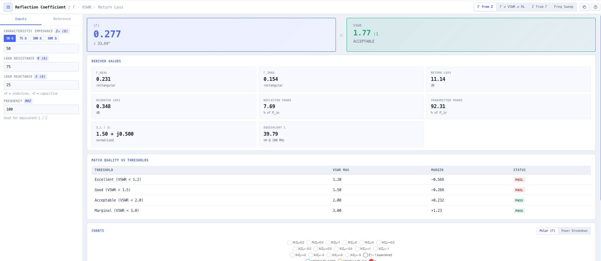
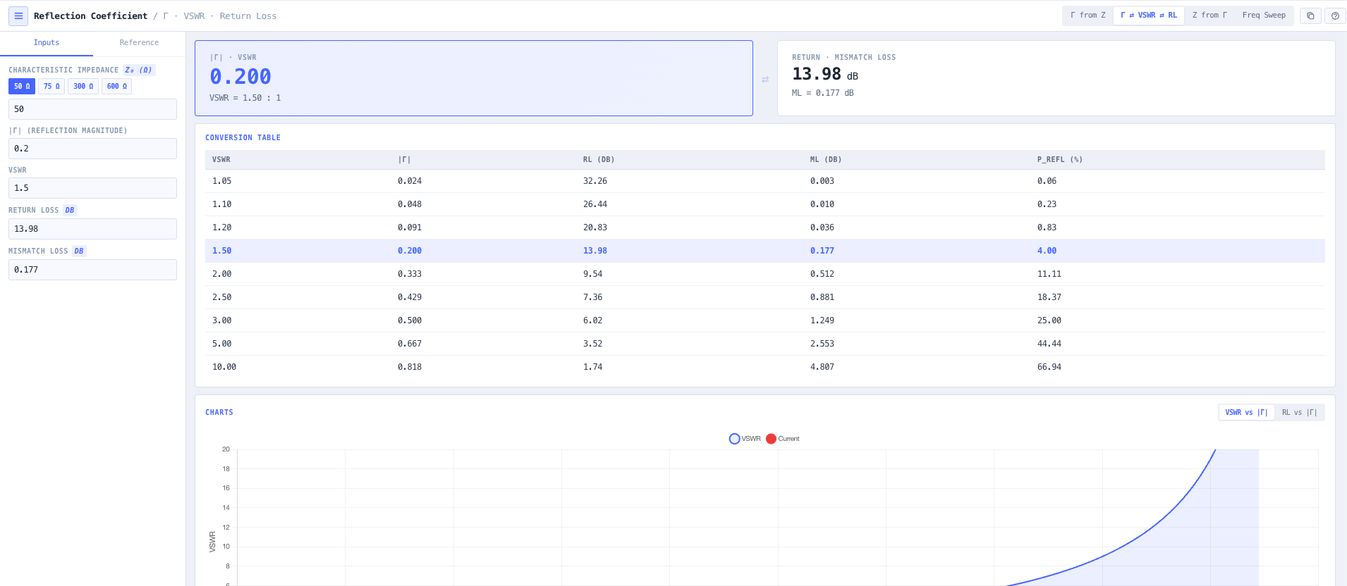
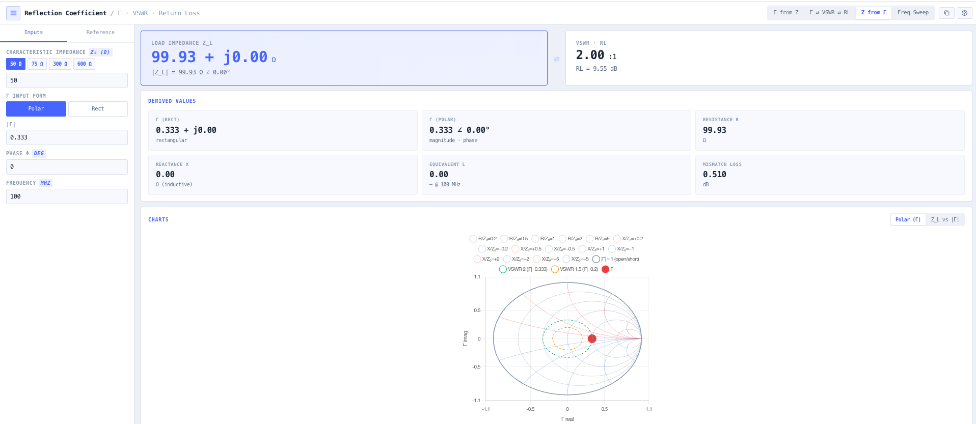
The noIM₃ Reflection Coefficient Calculator handles the relationship in every direction. Forward calculation from a complex load impedance Z load equals R plus jX with characteristic impedance Z naught (50 ohm default, 75 ohm cable TV, 300 ohm twinlead, or any user defined value) returns Gamma in both rectangular (Gamma real plus j Gamma imaginary) and polar (magnitude Gamma at angle phi) form. Bidirectional VSWR, return loss, and mismatch loss conversion edits any field and updates the others instantly. Inverse mode recovers Z load from a measured Gamma or S11 (rectangular or polar form) using Z load equals Z naught times (1 plus Gamma) divided by (1 minus Gamma), reporting resistance, reactance, and equivalent series L or C at a chosen frequency.

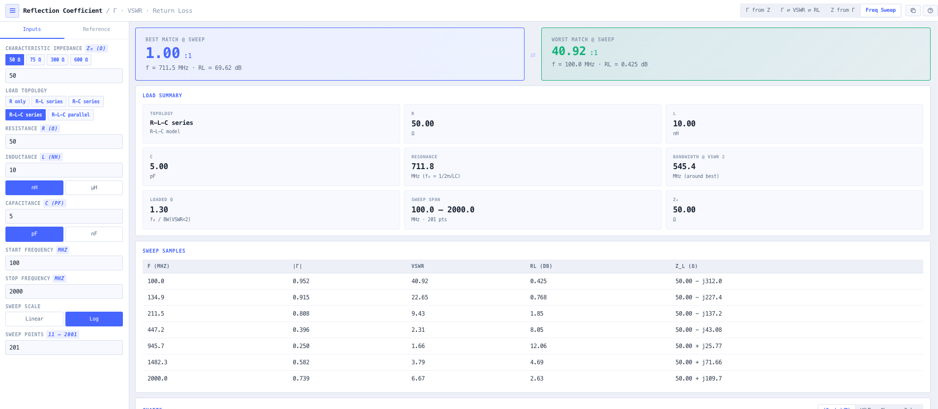
Frequency sweep mode models a load as a series or parallel R L C combination (or any subset, R, R L, R C, etc) and sweeps across a configurable frequency band. Output covers magnitude of S11 in dB, S11 phase in degrees, VSWR versus frequency, and the polar (Smith style) trajectory of Gamma across the band with constant resistance and constant reactance loci overlaid. Sweep metrics surface best and worst VSWR, the resonant frequency where Gamma magnitude is minimum, the contiguous bandwidth where VSWR stays below 2, and the loaded Q of the response. Useful for antenna resonance characterisation, filter passband and stopband visualisation, connector return loss validation, and any matching work where the design discussion needs both numerical metrics and visual confirmation in one workspace.

Capabilities

Complex Gamma from load impedance

Forward calculation Gamma equals (Z load minus Z naught) divided by (Z load plus Z naught) for any complex load Z load equals R plus jX. Output in both rectangular (Gamma real plus j Gamma imaginary) and polar (magnitude Gamma at angle phi) form simultaneously, plus derived VSWR, return loss, mismatch loss, and reflected power as a percentage of incident power.

Bidirectional VSWR, return loss, and mismatch loss conversion

VSWR equals (1 plus magnitude Gamma) divided by (1 minus magnitude Gamma). Return loss equals minus 20 log of magnitude Gamma. Mismatch loss equals minus 10 log of (1 minus magnitude Gamma squared). Edit any of these fields and the others update instantly. Useful for cross referencing network analyser readings, datasheet specifications, and link budget loss allocations across the four representations.

Inverse impedance recovery

Given Gamma in rectangular or polar form, or an S11 magnitude and phase from a vector network analyser measurement, the calculator solves Z load equals Z naught times (1 plus Gamma) divided by (1 minus Gamma) and reports resistance, reactance, and equivalent series L or C at a chosen frequency. Useful for converting VNA measurements directly to component values during matching network design.

Series and parallel R L C load modelling

Model a load as series R L C, parallel R L C, R L only, R C only, pure R, or any other subset. Sweep across a configurable frequency band and visualise how the impedance and Gamma evolve with frequency. Useful for understanding antenna resonance, filter passband behaviour, and the impedance signature of physical connectors, transitions, and parasitic elements.

Frequency sweep visualisation

Charts cover magnitude of S11 in dB versus frequency (the network analyser screen view), S11 phase in degrees, VSWR versus frequency, and the polar Smith style trajectory of Gamma across the band. Constant resistance and constant reactance loci overlay the polar plot for direct interpretation of the impedance evolution. Useful for antenna and filter characterisation work where the question is what the device looks like across the operating band rather than at one frequency.

Sweep metrics

Best and worst VSWR across the swept band. Resonant frequency where magnitude of Gamma is minimum. Contiguous bandwidth where VSWR stays below 2 (the standard match bandwidth metric). Loaded Q of the response (centre frequency divided by 2 to 1 VSWR bandwidth). Together they cover the metrics that go into antenna and filter datasheets so vendor claims can be verified directly.

Characteristic impedance presets

50 ohm RF and microwave default. 75 ohm cable TV and broadcast. 300 ohm balanced twinlead and folded dipole. Custom user defined for unusual systems. Z naught is applied throughout the forward and inverse calculation, so non standard impedance work is fully supported without manual unit handling.

VSWR threshold reference table

Built in conversion table covering common VSWR values (1.05, 1.1, 1.2, 1.5, 2.0, 2.5, 3.0, 5.0, 10.0) with the corresponding magnitude of Gamma, return loss in dB, mismatch loss in dB, and reflected power percentage. Useful as a sanity check during design discussions and as quick reference for engineers learning the relationships.

Browser only computation

Runs entirely in your browser. No impedance values, S11 measurements, or design data are submitted to a server. Useful for commercially confidential antenna and matching network design, defence and intelligence RF development, and environments where information security policy prohibits sending engineering data to third party services.

Standards & methodology

  • IEEE 145. Standard definitions of terms for antennas
  • IEEE 287. Precision coaxial connectors
  • 50 ohm RF and microwave reference impedance
  • 75 ohm cable TV and broadcast reference impedance
  • 300 ohm balanced line reference impedance
  • Smith chart constant resistance and constant reactance loci convention

When to use this tool

  • Antenna matching and tuning from HF through millimetre wave
  • Feeder and cable VSWR analysis
  • Filter, duplexer, and combiner characterisation
  • Connector and transition return loss assessment
  • Interpreting vector network analyser S11 measurements
  • Link budget mismatch loss allocation
  • Educational visualisation of Gamma, VSWR, and Smith chart geometry
  • Recovering equivalent component values from a measured S11
  • Sanity checking vendor antenna or filter datasheet claims against the underlying physics
  • Designing matching networks for complex impedance loads
  • Validating that an antenna feedpoint impedance matches the design target across the operating band
  • Producing engineering evidence for antenna acceptance testing and licence applications

Is this the right tool for you?

Reach for the Reflection Coefficient Calculator in any of the following situations.

  • You have a complex load impedance from an antenna feedpoint measurement and need to compute the resulting reflection coefficient and VSWR before designing the matching network.
  • You have a measured S11 magnitude and phase from a vector network analyser and need to recover the underlying load impedance for matching network synthesis.
  • You are characterising an antenna across its operating band and need to see VSWR versus frequency, the resonant frequency, and the contiguous VSWR less than 2 bandwidth.
  • You are validating a filter passband response and need to confirm the worst case VSWR within the passband against the datasheet specification.
  • You are reading a network analyser screen showing return loss in dB and want to convert it to VSWR or magnitude of Gamma without doing logs in your head.
  • You are quoting mismatch loss in a link budget and need to convert from VSWR to mismatch loss in dB at the operating frequency.
  • You are sanity checking a vendor antenna VSWR claim across a wide operating band and want to model the antenna as a series R L C network and confirm the predicted VSWR matches the spec.
  • You are designing a matching network for a non 50 ohm load and need to see how Gamma evolves with the matching network components in real time.
  • You are validating a 75 ohm cable TV feeder against the matched load and need to confirm that the reflection coefficient is acceptable across the channel range.
  • You are evaluating connector or transition return loss against a vendor datasheet and need to see the sweep response across the operating band.
  • You are training new RF engineers in transmission line theory and want a teaching tool that exposes the Gamma to VSWR to return loss to mismatch loss relationships side by side with a polar Smith style trajectory.
  • You are diagnosing an antenna that was working and is now off resonance and need to compare current VSWR sweep against the design baseline to identify the shift.
  • You are responsible for an antenna acceptance test and need engineering evidence covering Gamma, VSWR, return loss, and mismatch loss across the full operating band.
  • You are evaluating the impact of a parasitic capacitance or stray inductance on an otherwise resistive load and want to see how it shifts the resonant frequency and the polar trajectory.
  • You are operating under a security regime that prohibits sending design data to third party services and need a reflection coefficient calculator that runs entirely in your browser.

Frequently asked questions

What is the reflection coefficient and how is it computed?

The reflection coefficient Gamma is the complex ratio of the reflected voltage wave to the incident voltage wave at a transmission line termination. For a load impedance Z load and characteristic impedance Z naught, Gamma equals (Z load minus Z naught) divided by (Z load plus Z naught). It is a complex number with magnitude between 0 (perfect match) and 1 (total reflection) and an angle that captures the phase of the reflection. All other mismatch metrics (VSWR, return loss, mismatch loss) derive from the magnitude of Gamma.

How are VSWR, return loss, and mismatch loss related?

VSWR equals (1 plus magnitude Gamma) divided by (1 minus magnitude Gamma). Return loss in dB equals minus 20 log of magnitude Gamma (positive numbers, larger is better). Mismatch loss in dB equals minus 10 log of (1 minus magnitude Gamma squared). They are three different views of the same underlying reflection magnitude. VSWR is what wattmeters and antenna analysers report. Return loss is what network analysers report. Mismatch loss is what link budgets care about. The calculator updates all three simultaneously.

How do I recover impedance from a measured Gamma or S11?

Z load equals Z naught times (1 plus Gamma) divided by (1 minus Gamma). Given Gamma in rectangular or polar form (or S11 from a network analyser), the inverse mode computes the recovered load impedance and reports resistance, reactance, and equivalent series L or C at a chosen frequency. Useful for converting VNA measurements directly into component values during matching network design.

What is the difference between return loss and mismatch loss?

They look similar but represent different things. Return loss in dB is minus 20 log of magnitude Gamma and quantifies the magnitude of the reflection (large positive numbers indicate a good match). Mismatch loss in dB is minus 10 log of (1 minus magnitude Gamma squared) and quantifies the dB cost in delivered power against an ideal matched load. Return loss is what a network analyser reports. Mismatch loss is what the link budget cares about. The two are not interchangeable.

How does the frequency sweep mode work?

Model the load as a series or parallel R L C combination (or any subset) and sweep across a configurable frequency band. The calculator computes the impedance at every frequency point, the resulting Gamma, and the derived VSWR. Output covers magnitude of S11 in dB, S11 phase, VSWR versus frequency, and the polar Smith style trajectory. Useful for antenna and filter characterisation, where the question is what the device looks like across the band rather than at one frequency.

What does loaded Q tell me?

Loaded Q is the centre frequency divided by the 2 to 1 VSWR bandwidth. It captures how sharply the impedance match peaks at resonance. High Q antennas (for example small loops, high gain helicals) have narrow operating bandwidth. Low Q antennas (for example log periodic, wideband biconical) have broad bandwidth. The tradeoff between Q and bandwidth is fundamental to antenna design and the calculator surfaces it explicitly.

How does this relate to the VSWR Calculator?

The VSWR Calculator focuses on quick conversion between forward and reflected power, VSWR, return loss, and mismatch loss as scalar quantities, with quality presets for system health assessment. The Reflection Coefficient Calculator covers the full complex Gamma analysis including impedance, polar Smith style trajectory, and frequency sweep modelling for matching network design. Use the VSWR Calculator for fast bench measurements and quick conversion. Use the Reflection Coefficient Calculator for matching network design and network analyser interpretation.

Does any data leave my browser?

No. The calculator runs entirely in your browser. No impedance values, S11 measurements, or design data are submitted to a server. Useful for commercially confidential antenna and matching network design, defence and intelligence RF development, and environments where information security policy prohibits sending engineering data to third party services.