A directional coupler is one of the most useful passive parts in an RF system, and almost every job an integrator gives it is a level problem rather than a design problem. You tap a transmitter to feed a monitor, a power meter or a spectrum analyser. You inject a pilot or a second carrier into a running line. You put a dual directional coupler in front of an antenna to read forward and reflected power during commissioning. In each case the question is the same: given the coupler figures on the datasheet, what power turns up where, and is it the level you need.
The noIM3 Directional Coupler Calculator answers that question directly. It is scoped for systems integrators and does not touch coupled line design. There is nothing here about even and odd mode impedances or section lengths. Instead it takes the figures a datasheet actually gives you, coupling, insertion loss, directivity and isolation, and turns them into the port levels, the part selection and the measurement accuracy you work with on site.
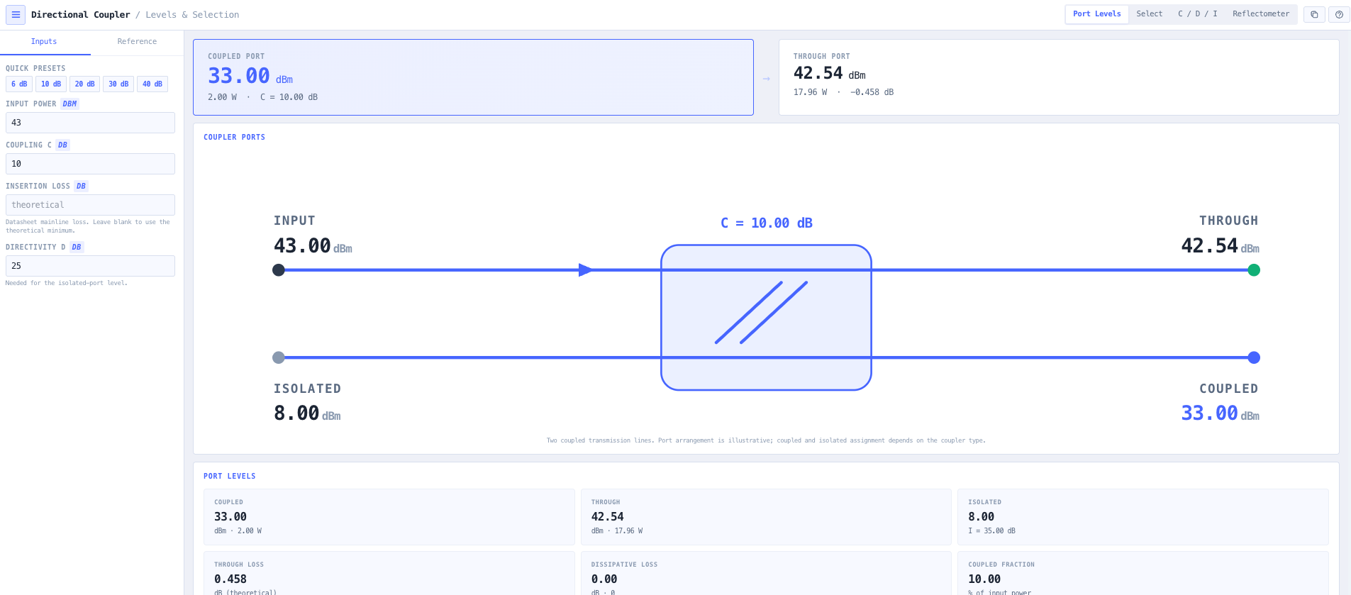
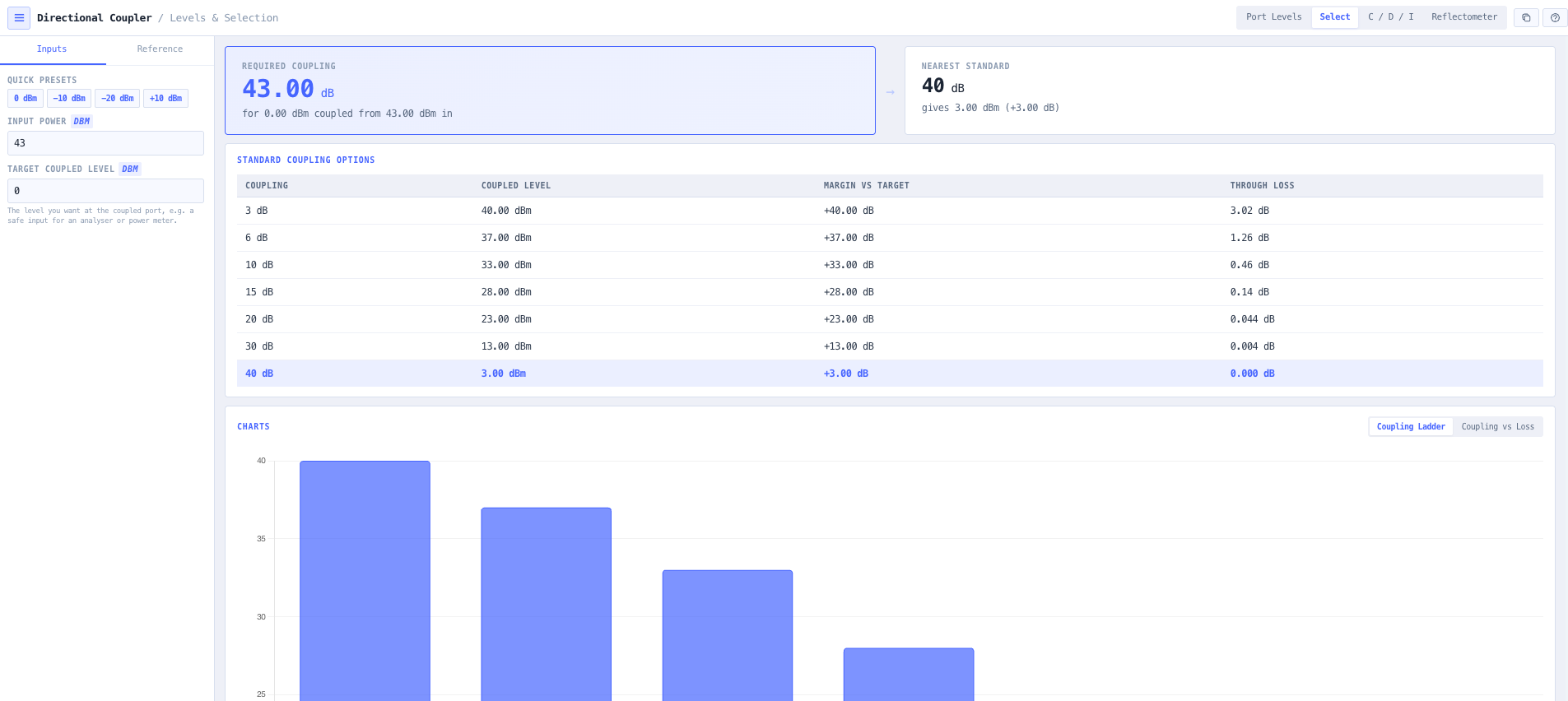
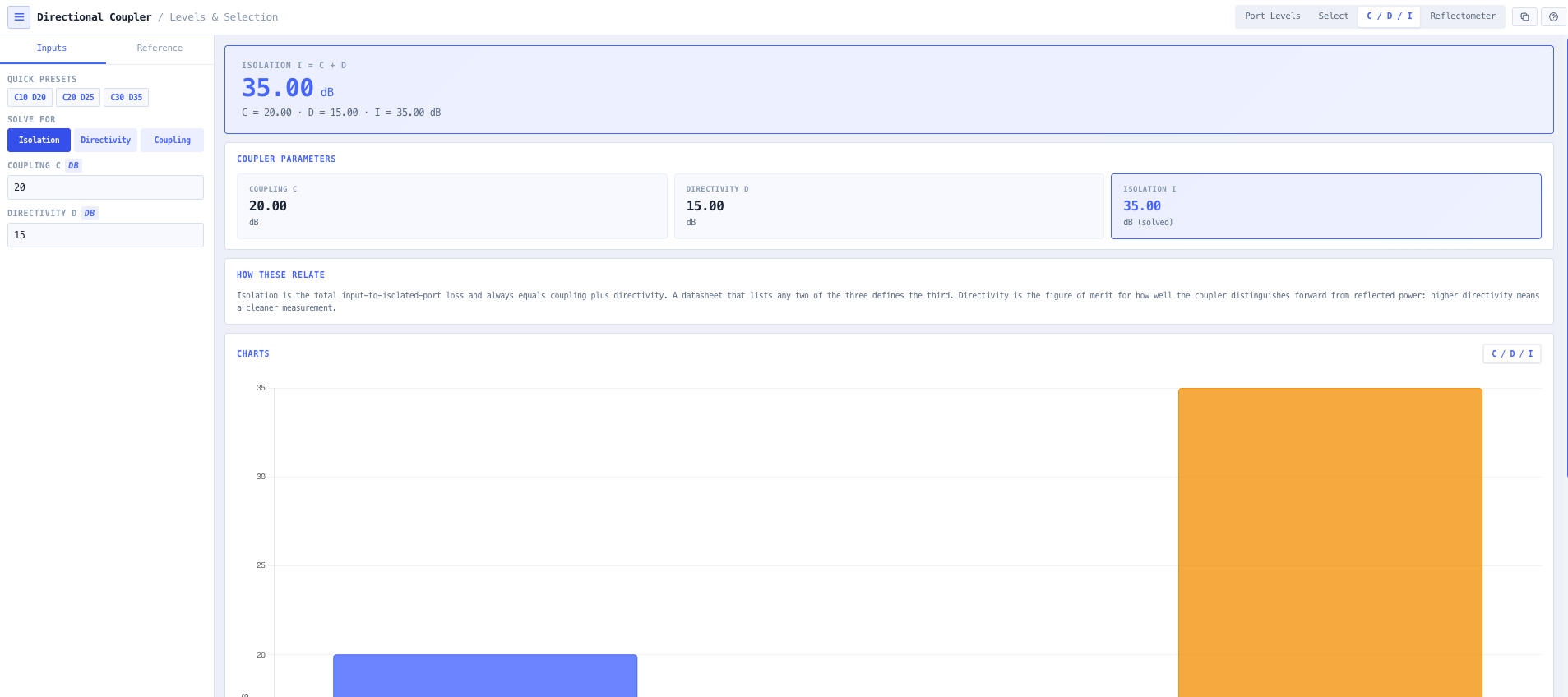
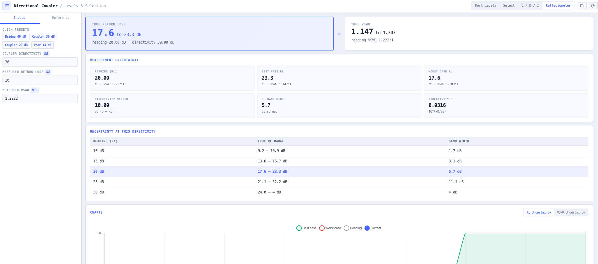
Four modes cover the everyday work. Port Levels reports the power at the through, coupled, isolated and dissipated ports for a given input, with a live diagram. Select Coupling turns a target tap level into the exact coupling required and the nearest standard value. The solver reconciles the coupling, directivity and isolation relationship from any two figures. Reflectometer Accuracy shows how much a coupler directivity limits a return loss measurement, which is the difference between a VSWR reading you can trust and one you cannot.