Electrical System Design

Earthing & Lightning Protection Calculator

Design and check the earthing and lightning protection of a comms tower, rooftop, shelter, or cabinet — earth-electrode resistance from soil resistivity, lightning risk to a protection level, rolling-sphere protection of mast-mounted antennas, and bonding and surge protection.

Free forever on a Standard account. No credit card.

Overview

Earthing and lightning protection on a communications site is its own discipline. The earth electrode has to reach a low resistance in whatever soil the site sits on, the tower or rooftop is a tall, exposed, lightning-attractive structure full of sensitive electronics, the antennas are mounted up where a direct strike is most likely, and every metallic service entering the shelter is a path for surge current. A site that earths and bonds poorly does not fail gracefully — it loses equipment to a nearby strike, raises dangerous touch voltages at the tower base on a power fault, or couples lightning energy straight into the radios.

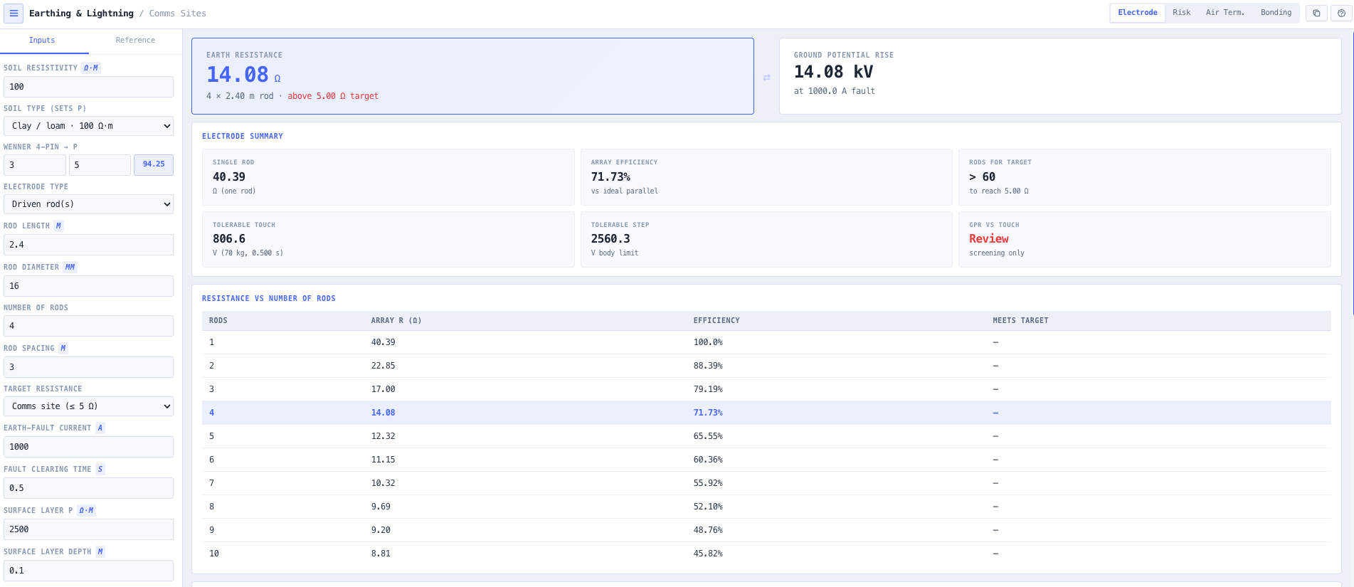
The noIM₃ Earthing & Lightning Protection Calculator is built for exactly that work, for the systems integrator rather than the substation or building-LPS specialist. It starts from the earth electrode: resolve the resistance of driven rods (single, or an array with the mutual coupling between rods properly accounted for), a horizontal strip, or an area grid or ring using the IEEE 80 equation, from a soil resistivity you enter directly, pick from a soil type, or reduce from a Wenner four-pin survey. It tells you how many rods reach your target resistance and screens the ground potential rise against the IEEE 80 tolerable touch and step voltages.

From there it covers the three things that decide a comms site’s lightning design. A risk mode estimates the collection area and the expected number of direct strikes from the ground flash density and screens them against a tolerable frequency to recommend a Lightning Protection Level. An air-termination mode applies the rolling-sphere method to check whether mast-mounted antennas sit inside the protected zone, sizes the down-conductors, and computes the separation distance for parallel feeders. A bonding mode picks an ITU-T K.27 topology, sizes the bonding conductors, works out the lightning current each service carries, and coordinates the surge protective devices against the equipment withstand. Everything runs in the browser, copies to the clipboard for the design file, and is labelled as planning-grade guidance to confirm by measurement and a full risk assessment.

Capabilities

Earth-electrode resistance from soil resistivity

Resolve the earth resistance of a single driven rod (Dwight / IEEE 142), a rod array, a horizontal strip (BS 7430), or an area grid / ring (IEEE 80 Sverak). Soil resistivity is entered directly, picked from a soil type, or reduced from a Wenner four-pin survey, so the result is anchored to the soil you actually have rather than a blanket assumption.

Rod arrays with real mutual coupling

Adding rods does not simply divide the resistance by the number of rods, because each rod sits in the potential field of the others. The tool combines the rod self-resistance with the average mutual resistance, so the array efficiency falls as rods are packed closer, shows the resistance-versus-rod-count curve, and finds the smallest rod count on a given spacing that reaches the target.

Ground potential rise and touch / step voltages

Enter the prospective earth-fault current and clearing time and the tool computes the ground potential rise and the IEEE 80 tolerable touch and step voltages for a 50 or 70 kg body, with a surface-layer derating for a crushed-rock or asphalt finish — a personnel-safety screen at the tower base.

Lightning risk to a protection level

Estimate the structure collection area and the expected number of direct strikes from the ground flash density (entered, or from thunderstorm-days) and a location factor, screen against a tolerable frequency, and recommend a Lightning Protection Level from I to IV by the simplified AS/NZS 1768 / IEC 62305-2 method.

Rolling-sphere protection of antennas

Apply the rolling-sphere radius for the protection level to a vertical air terminal at the mast top, get the protected radius at the antenna height, and check whether an antenna at a given outrigger offset sits inside the protected zone, with a protected-zone chart that makes the geometry obvious.

Down-conductors and separation distance

Size the number of down-conductors for the structure perimeter at the level spacing, never fewer than two, and compute the separation (isolation) distance from the induced-voltage, current-distribution and material coefficients, so you know whether a parallel coax or feeder run must be bonded to the down-conductor.

Bonding topology and conductor sizing

Pick a common-bonding-network, mesh, isolated-bonding-network or single-point topology per ITU-T K.27, and size the lightning-current-carrying and functional equipotential bonding conductors against the IEC 62305 / AS/NZS 1768 minimums for copper, aluminium or galvanised steel.

Surge protection coordination

Work out the lightning current each AC, DC, coax and data line carries from the current-sharing rule, recommend an SPD type for each, and coordinate the SPD protection level against the equipment impulse withstand with a recommended margin so the let-through voltage stays safely below what the equipment can take.

Standards & methodology

  • AS/NZS 1768:2021 lightning protection (risk, protection level, air termination, bonding)
  • IEC 62305-1 to 4 protection against lightning (risk, physical damage, electronic systems)
  • IEEE Std 80 grounding safety (grid resistance, tolerable touch and step voltages)
  • IEEE Std 142 / BS 7430 earth-electrode resistance (driven rods, strips)
  • AS/NZS 3000 wiring rules (earthing and equipotential bonding)
  • ITU-T K.27 bonding configurations and earthing inside a telecom building
  • ETSI EN 300 253 earthing and bonding of telecommunication equipment
  • ANSI/TIA-607-D (J-STD-607) generic telecommunications bonding and grounding

When to use this tool

  • Designing the earth electrode for a new comms tower or monopole compound
  • Checking whether a rod array will reach a target earth resistance in measured soil
  • Reducing a Wenner four-pin survey to a design soil resistivity
  • Sizing an area earth grid or ring for an equipment compound
  • Screening ground potential rise and touch / step voltages at a tower base
  • Screening whether a site needs lightning protection and to what level
  • Checking whether mast-mounted antennas sit inside the rolling-sphere protected zone
  • Sizing the number of down-conductors for a structure perimeter
  • Working out the separation distance for a parallel coax or feeder run
  • Selecting an ITU-T K.27 earthing topology for a comms shelter
  • Sizing lightning and functional bonding conductors for a main earth bar
  • Coordinating surge protective devices against equipment impulse withstand on power, coax and data lines

Is this the right tool for you?

Reach for the Earthing & Lightning Protection Calculator in any of the following situations.

  • You are designing the earth electrode for a new monopole compound and need to know how many rods, at what spacing, will reach a 5 Ω target in the site’s clay soil.
  • You have a Wenner four-pin survey from the site and need to reduce it to a design soil resistivity before sizing the electrode.
  • The site is on high-resistivity rock and a rod array is hitting diminishing returns; you want to see the array efficiency and compare it with a horizontal strip or a ring electrode.
  • You need to screen the ground potential rise and tolerable touch and step voltages at the tower base for a given earth-fault current and clearing time.
  • A client asks whether their rooftop installation needs lightning protection; you need a defensible screening of the strike frequency and a recommended protection level.
  • A tall greenfield mast is clearly lightning-exposed and you need to establish the Lightning Protection Level before sizing the air termination and down-conductors.
  • You are mounting antennas part-way up a mast and need to confirm they sit inside the rolling-sphere protected zone of a finial at the mast top, or work out how tall the finial must be.
  • You need to size the number of down-conductors for the structure perimeter and check the separation distance for a coax run that parallels a down-conductor.
  • You are bonding a comms shelter and need to choose between a common bonding network and an isolated bonding network and size the bonding conductors.
  • You need the lightning current each external service carries on a direct strike to specify the impulse rating of the service-entrance SPDs.
  • You are coordinating surge protective devices on the AC, DC, coax and data lines and need to confirm the SPD protection level stays below the equipment impulse withstand with margin.
  • You are writing an earthing and lightning-protection section for a tender or design review and want a clear, standards-anchored first-pass set of figures to attach.
  • You are working on a security-restricted site and need a tool that runs entirely in the browser and sends nothing to a server.

Frequently asked questions

What earth resistance should I aim for on a comms site?

It depends on the site and the equipment. A common general target for an LV installation earth is 10 Ω or less, many communications sites aim for 5 Ω or less, and sensitive or co-located sites sometimes specify 1 Ω or less. The right figure comes from the equipment requirements, the protective-device disconnection, and the lightning design, not from a single rule, so the tool lets you set the target and shows what electrode it takes to reach it. Whatever the design figure, the installed resistance must be confirmed by measurement.

Why does adding more rods not divide the resistance by the number of rods?

Because the rods are not independent. Each rod sits in the potential field of the others, so the effective resistance of an array is higher than a naive divide-by-n suggests. The tool combines the rod self-resistance with the average mutual resistance between rods, which is why the array efficiency falls as rods are packed closer together, and why spreading rods further apart (ideally by at least their length) recovers more of the benefit.

How do you reduce a Wenner four-pin survey to a resistivity?

The apparent soil resistivity is ρ = 2π·a·R, where a is the equal probe spacing and R is the measured resistance, and the result represents the soil to a depth of roughly the probe spacing. Surveying at several spacings reveals how the resistivity changes with depth, which matters when a deep rod passes through a low-resistivity layer. The tool reduces a single spacing for you and you apply it as the design resistivity.

Is the lightning risk a full IEC 62305-2 assessment?

No. The risk mode is the simplified screening method: it estimates the collection area and the expected number of direct strikes and compares them against a tolerable event frequency to recommend a Lightning Protection Level. It is intended to establish quickly whether protection is needed and at roughly what level. The final determination of protection measures should come from a full R1 / R2 risk assessment to AS/NZS 1768 or IEC 62305-2 with the site-specific loss and probability factors.

How does the rolling-sphere method decide whether an antenna is protected?

An imaginary sphere of a radius set by the protection level (20 m for Level I up to 60 m for Level IV) is rolled over the structure; anything it cannot touch is protected. For a vertical air terminal that gives a protected radius at each height, and the tool checks whether the antenna, at its height and outrigger offset from the mast, falls inside that radius. If it does not, you either raise the air-terminal finial, add a terminal, or move the antenna.

What is the separation distance and why does it matter?

When lightning current flows down a down-conductor it induces a high voltage on nearby metalwork. The separation (isolation) distance is the minimum air or material gap that keeps that induced voltage from flashing over to a parallel conductor such as a coax or feeder. If the run is closer than the separation distance, it must be bonded to the down-conductor so the two rise together rather than flashing over. The tool computes it from the protection level, the number of down-conductors, the material between, and the run length.

How are the surge protective devices coordinated?

Two ways. First, the impulse current rating must be adequate for the lightning current that line carries, which the tool estimates from the current-sharing rule (about half the stroke goes to the earth electrode and the rest divides among the services). Second, the SPD voltage-protection level Up, plus the volt-drop on its connecting leads, must stay below the equipment’s rated impulse withstand Uw. Good practice keeps Up at or below 80 percent of Uw, which is the margin the tool checks.

Does any data leave my browser?

No. The calculator runs entirely in your browser. No site data is submitted to a server, which suits commercially confidential work and security-restricted communications sites.