
All seven uplink downlink configurations with real subframe patterns
Table 4.2-2 in full, with the actual D, S and U sequence rather than a nominal percentage split. The pattern is what decides latency as well as throughput.
All seven TDD uplink downlink configurations and eleven special subframe configurations from 3GPP TS 36.211, with the guard period and the timing limit it puts on the cell radius, and the frame structures sections 39 and 40 of the Australian Fixed Licence Determination can require at 3.4 GHz.
Free forever on a Standard account. No credit card.
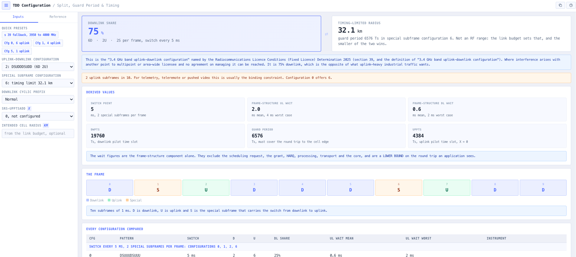
Industrial traffic pushes. Autonomous haulage telemetry, teleremote video and fixed cameras all send uplink, and the LTE TDD configurations were designed for consumer traffic that pulls. Configuration 2, the common default, gives two uplink subframes in ten. Configuration 0 gives six. Choosing wrongly costs a factor of three on the direction the design depends on, and no amount of extra sites recovers it.
The special subframe is the other half of the choice, and it is the half that is usually missed. Its guard period has to cover the round trip to the cell edge, so it is a hard bound on cell size that no link budget will ever surface. A cell can be perfectly well covered and still fail, because the uplink arrives after the switch. The tool ranks all eleven configurations by the timing limit their guard period sets, from about 107 km down to about 11 km with no extra SRS symbols, which is a range wide enough that the choice cannot be left to a default. Enter the radius the link budget needs and it says whether the guard period or the RF range is the constraint.
There is an Australian dimension here that no other tool has. The Radiocommunications Licence Conditions (Fixed Licence) Determination 2025 defines the "3.4 GHz band uplink-downlink configuration" as one consistent with BOTH uplink downlink configuration 2 of TS 36.211 Table 4.2-2 AND special subframe configuration 6 of Table 4.2-1. Section 39 can require a point to multipoint licensee in 3950 to 4000 MHz to adopt it where interference arises with another licensee and no agreement on managing it can be reached.
That configuration is 75 per cent downlink, with two uplink subframes in ten, on the 3950 to 4000 MHz block. A design built around configuration 0 and its six uplink subframes has no fallback if section 39 is invoked, and finding that out after deployment is expensive. Section 40 is the lower-block counterpart: at a Schedule 1 urban-area site in 3400 to 3475 MHz with an adjacent spectrum licence, the frame structure must follow the spectrum licensee's. The tool resolves the section 39 definition against the actual 3GPP tables, reports the split and the 32.1 km timing limit that follow from it, and states both conditions.
Table 4.2-2 in full, with the actual D, S and U sequence rather than a nominal percentage split. The pattern is what decides latency as well as throughput.
Table 4.2-1 for both normal and extended cyclic prefix, with the DwPTS, guard period and UpPTS symbol counts that each one produces.
The guard period has to cover the round trip to the cell edge. That makes it a limit on cell size that no link budget will ever show you, and it is the reason a well covered cell can still fail at range. It is named a timing limit, not a range, because the link budget sets the range separately and the smaller of the two is the cell.
Enter the radius the link budget needs and the tool says which constraint wins: the guard period covers the cell and the RF range decides, or the design is timing-limited. Where it is, the special subframe configurations that would reach the cell are listed, and the timing limit table says yes or no for every row.
The wait for the next subframe carrying your direction, mean and worst case. On an uplink heavy design this is a floor that no scheduler tuning gets under. It excludes the scheduling request, the grant, HARQ, processing, transport and the core, and the page says so next to the figure.
The subframe sequence drawn out, because the pattern matters as much as the count. Two configurations with the same split can have very different worst case waits, and the comparison table is grouped by switch-point family so the seven are not read as one ordered list.
Section 39 of the Fixed Licence Determination 2025 names a configuration by reference to two separate 3GPP tables. The tool resolves that definition and reports the split and the 32.1 km timing limit it implies, which is the exposure a 3950 to 4000 MHz design carries. Section 40, the lower-block obligation to follow an adjacent spectrum licensee's frame structure, is stated alongside it so neither is mistaken for a universal rule.
Additional sounding reference signal symbols come out of the guard period, so they cost cell radius. The effect is shown for 2 and 4 symbols, and the combinations TS 36.211 clause 4.2 says a UE is not expected to have are reported as not configurable rather than as a negative reach.
Some special subframe configurations have no form for a given cyclic prefix. They are reported as undefined rather than omitted from the table, because a silently missing row reads as an oversight rather than as a fact about the specification.
Because the uplink has to arrive before the base station switches back to transmit. The guard period covers the round trip propagation delay to the cell edge, so it sets a hard maximum radius independent of signal strength. A cell that is perfectly well covered by the link budget will still fail if the uplink lands after the switch, and nothing in a coverage prediction shows that.
That depends on the direction the application actually depends on, which for most industrial traffic is uplink. Configuration 2, the common default, gives two uplink subframes in ten. Configuration 0 gives six. Autonomous haulage telemetry, teleremote video and fixed cameras all push, so inheriting a consumer default costs a factor of three on the direction that matters and no amount of extra sites recovers it.
The Radiocommunications Licence Conditions (Fixed Licence) Determination 2025 defines the "3.4 GHz band uplink-downlink configuration" as one consistent with both uplink downlink configuration 2 of TS 36.211 Table 4.2-2 and special subframe configuration 6 of Table 4.2-1. That is 75 per cent downlink with two uplink subframes in ten, and a timing limit of about 32.1 km on the cell radius. It is a fallback, not a universal requirement.
Section 39 can require a point to multipoint licensee in 3950 to 4000 MHz to adopt it where interference arises with another licensee and no agreement on managing that interference can be reached. It is worth knowing before deployment rather than after: a design built around configuration 0 and its six uplink subframes has no fallback if section 39 is invoked.
Yes. DwPTS carries downlink data, so a special subframe with a long guard period gives up downlink capacity to buy cell reach. That is the trade the table makes visible: the configurations with the longest reach are the ones that hand back the most capacity, and picking one without seeing the other side of it is how a design ends up short in both.
No. It is the largest radius the guard period can serve, and the cell is the smaller of that and the range the link budget gives. Enter the radius the link budget needs and the tool says which of the two is the constraint. A cell inside the timing limit is decided by RF; a cell beyond it is timing-limited, and the special subframe configurations that would reach it are listed.
It is the number of additional sounding reference signal symbols in UpPTS, 2 or 4 per TS 36.331, or none. Each symbol is 2192 Ts taken out of the guard period, so the timing limit drops with it. TS 36.211 clause 4.2 lists the special subframe configurations a UE is not expected to be configured with for each value, because DwPTS and UpPTS would consume the whole subframe. The tool reports those as not configurable rather than as a negative reach.
Because some special subframe configurations have no defined form for a given cyclic prefix, and some cannot take the selected srs-UpPtsAdd. Omitting the row makes it look like an oversight in the tool. Reporting it as undefined or not configurable makes it clear that the specification does not define that combination, which is a different statement and the correct one.
No, and deliberately. The choice is a trade between uplink capacity, downlink capacity, latency and cell reach, and which of those dominates is a property of the deployment rather than of the standard. The tool puts all four on the same page for every configuration so the trade is made deliberately instead of inherited from a default.
Free forever on a Standard account. No credit card.