
Antenna Utilities

Antenna Effective Aperture Calculator

Effective aperture, gain, capture power, and required dish sizing in one workspace. Convert between gain and aperture, size dishes for a target received power, and solve aperture efficiency from measured gain. Built for systems integrators sizing VSAT, microwave backhaul, satellite ground stations, radar, and broadcast receive sites.

Free forever on a Standard account. No credit card.

Overview

Effective aperture is the physical equivalent of antenna gain. Where gain in dBi describes how much an antenna concentrates radiation relative to an isotropic radiator, effective aperture A effective describes the equivalent capture area presented to an incident wave. The two are equivalent through A effective equals G times lambda squared divided by 4 pi. Both forms are useful, but effective aperture is the natural form for capture power calculations (P received equals incident flux density times A effective) and for dish sizing (where the question is how many square metres of aperture do I need to deliver a target received power). Engineers move between gain and aperture constantly, and the conversion is where unit confusion and frequency dependence catches people out.

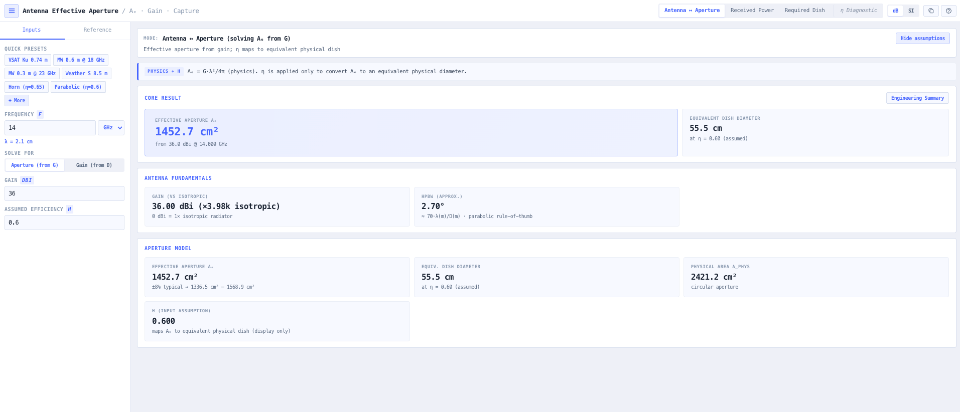
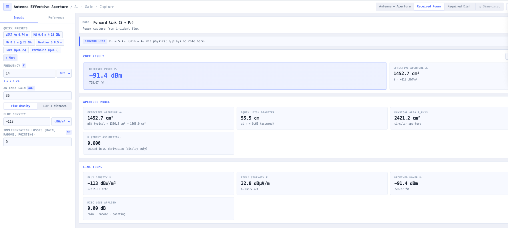
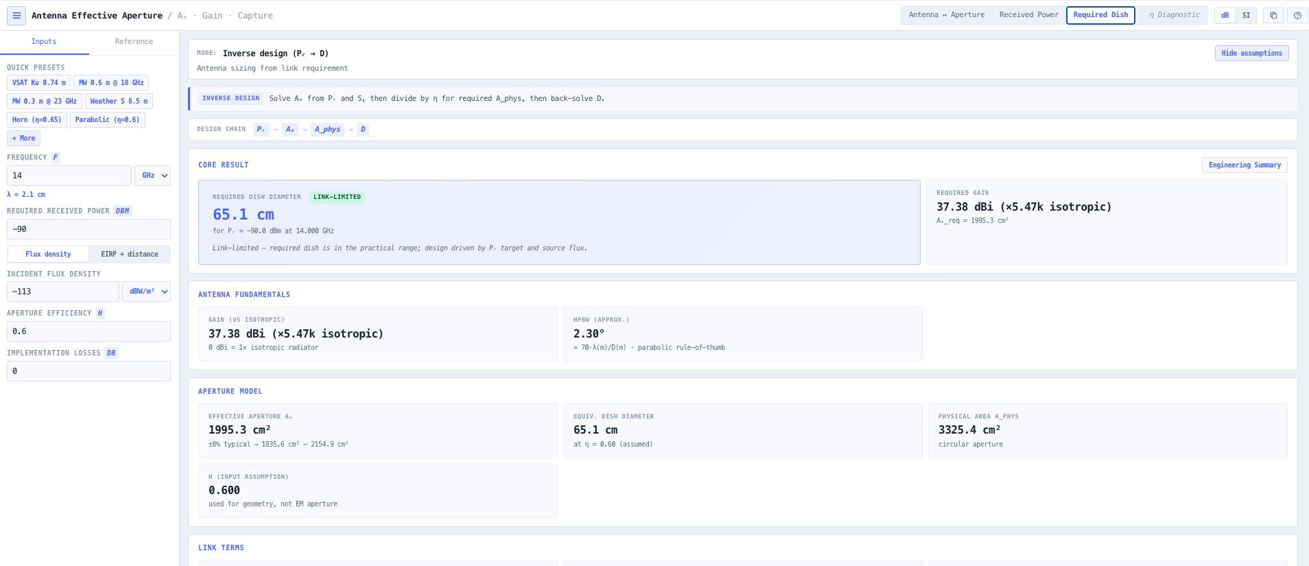
The noIM₃ Antenna Effective Aperture Calculator is purpose built for the systems integrator workflow. Three primary modes plus an efficiency diagnostic. Gain to aperture conversion (and back) at any frequency with a real time wavelength readout. Received power calculation from incident flux density (in W per square metre or dBW per square metre) or from transmitter EIRP plus slant range, with optional implementation loss as a single dB scalar covering rain, radome, and pointing degradation. Inverse design solver returns required effective aperture, equivalent dish diameter at an assumed efficiency, and the corresponding gain in dBi for a target received power. Useful for satellite ground station dish sizing, microwave receive site sizing, and any scenario where the question is what dish do I need to close this link.

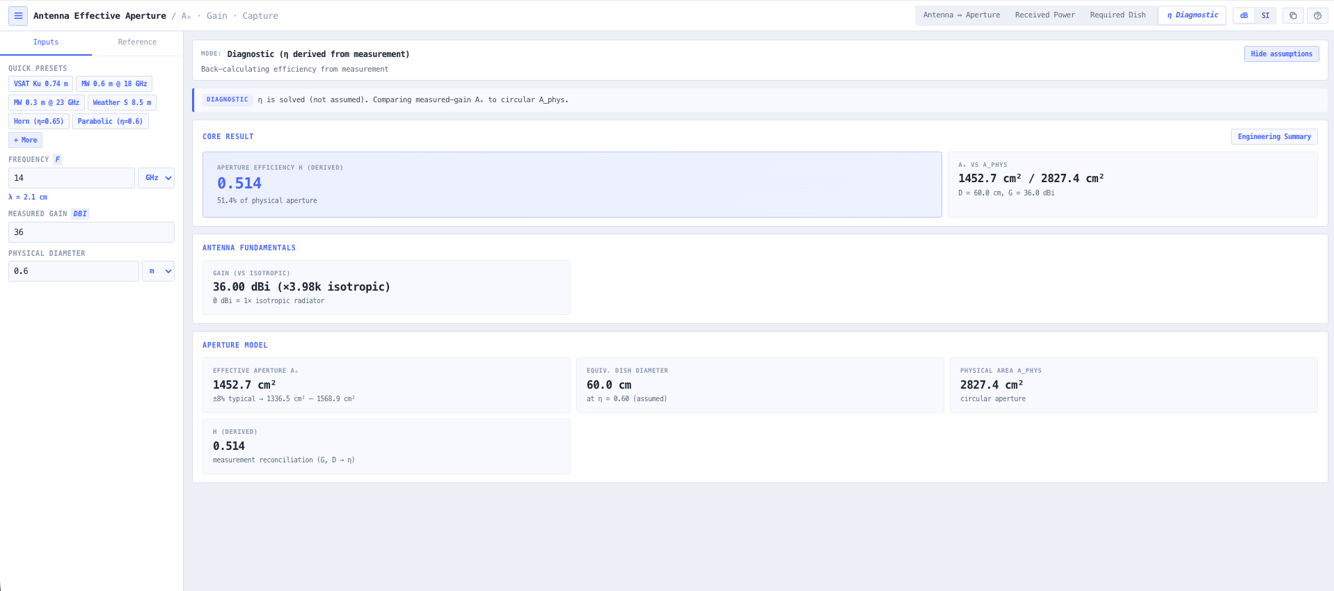
Aperture efficiency diagnostic mode returns the implied eta from measured gain and known physical diameter using G equals 4 pi times eta times physical area divided by lambda squared, with sanity warnings for unphysical values. Eta greater than 0.8 typically indicates measurement bias or aperture overestimate. Eta less than 0.3 typically indicates misalignment, blockage, surface tolerance issues, or a bad measurement. Tools many vendor datasheets never include. Reference data covers typical aperture efficiency per antenna family (60 to 70 per cent for prime focus dishes, 65 to 75 per cent for offset and Cassegrain, 50 to 70 per cent for horns, 50 to 70 per cent for printed arrays), wavelength by RF band (L through V), and common flux density references (GEO satellite downlink, GPS L1, FM broadcast). Every result includes an expandable derivation trace showing the lambda calculation, A effective, S, and P received steps.

Capabilities

Bidirectional gain and aperture conversion

Convert antenna gain in dBi at any frequency into effective aperture A effective in square metres using A effective equals G times lambda squared divided by 4 pi. Back calculate the equivalent dish diameter at an assumed aperture efficiency. Real time wavelength readout removes mental conversion from MHz or GHz to metres so the calculation is one input, one output.
Received power from flux or EIRP

Forward problem mode. Given an incident flux density in W per square metre or dBW per square metre, compute received power at the antenna terminal as P received equals S times A effective. Alternatively, given transmitter EIRP and slant range, compute the incident flux as S equals EIRP divided by 4 pi times R squared and the resulting received power. Optional implementation loss scalar applies rain, radome, and pointing degradation as a single dB number.

Required dish sizing (inverse design)

Inverse design mode. Given a target received power and the available signal source (flux density or EIRP plus distance), solve for the required effective aperture, equivalent dish diameter at an assumed efficiency, and the corresponding gain in dBi. The killer mode for satellite ground station dish sizing, microwave receive site sizing, and broadcast receive antenna design where the design question is what aperture closes the link.

Aperture efficiency diagnostic

Given a measured gain and a known physical diameter, compute the implied aperture efficiency eta using G equals 4 pi times eta times physical area divided by lambda squared. Sanity warnings flag eta greater than 0.8 (likely measurement bias or aperture overestimate) and eta less than 0.3 (likely misalignment, blockage, surface tolerance issues, or bad measurement). Useful for validating vendor datasheet gain claims and diagnosing antenna performance against expected efficiency.

EIRP to flux density bridge

Built in conversion from transmitter EIRP and slant range to incident flux density at the receive antenna using the inverse square law S equals EIRP divided by 4 pi R squared. Useful for satellite link work where the satellite EIRP is published but the engineer needs flux density at the ground station to size the dish.

Reference data tab

Built in reference covering typical aperture efficiency by antenna family (prime focus dishes, offset feed dishes, Cassegrain dishes, horn antennas, microstrip patch arrays). Wavelength by RF band from L through V. Common flux density references for sanity checking inputs (GEO satellite downlink at typical EIRP, GPS L1 at the antenna, FM broadcast field strength). Useful for fast first principles cross check against the calculation result.

Derivation trace

Every result includes an expandable how this was computed trace showing the wavelength calculation, A effective from G times lambda squared over 4 pi, flux density derivation if applicable, and final P received equals S times A effective. Useful for engineering documentation, design reviews, and reproducing the result independently.

Sanity warnings throughout

Aperture efficiency sanity warnings (eta greater than 0.8, eta less than 0.3). Diameter less than lambda over 2 warning for sub wavelength antenna geometry where the gain formula does not strictly apply. Near field distance check using 2 D squared over lambda for distance based calculations. Tools that vendor datasheets and many calculators do not include.

Browser only computation

Runs entirely in your browser. No antenna geometry, frequency, or design data is submitted to a server. Useful for commercially confidential antenna design, defence and intelligence ground station work, and environments where information security policy prohibits sending engineering data to third party services.

Standards & methodology

  • IEEE 145. Standard definitions of terms for antennas
  • A effective equals G times lambda squared divided by 4 pi (standard antenna theory relationship)
  • G equals 4 pi times eta times physical area divided by lambda squared (aperture antenna gain)
  • S equals EIRP divided by 4 pi R squared (free space spreading inverse square law)
  • Far field (Fraunhofer) distance 2 D squared over lambda

When to use this tool

  • Sizing satellite ground station dishes for required link margin and target received power
  • Estimating received power at the ground from a known satellite EIRP at slant range
  • Validating vendor claimed antenna gain against physical antenna size and aperture efficiency
  • Comparing dish, horn, patch array, and helical effective apertures at a given operating frequency
  • Quick capture power checks from spectrum analyser flux density readings
  • Teaching the relationship between gain, effective aperture, wavelength, and beamwidth
  • Sizing VSAT terminals for required carrier to noise at a given satellite EIRP
  • Sizing microwave receive site dishes against measured incident field
  • Producing antenna sizing evidence for satellite ground station acceptance
  • Diagnosing antenna underperformance against expected efficiency from physical diameter
  • Sizing radar receive antenna aperture for a target detection sensitivity
  • Sizing broadcast receive antenna for a target field strength reception

Is this the right tool for you?

Reach for the Antenna Effective Aperture Calculator in any of the following situations.

  • You are sizing a satellite ground station dish for a required link margin and need to convert a target gain or received power into a physical dish diameter at a realistic aperture efficiency.
  • You have a satellite EIRP from the operator (in dBW) and need to estimate received power at your candidate dish size before committing to procurement.
  • You are validating a vendor antenna datasheet that claims a particular gain at a particular diameter, and want to confirm whether the implied aperture efficiency is realistic.
  • You are sizing a VSAT terminal against a known satellite EIRP and slant range and need the required dish diameter for a target carrier to noise ratio.
  • You are comparing dish, horn, and patch array antennas at the same operating frequency and need a like for like effective aperture comparison.
  • You are reading a flux density value from a spectrum analyser and need to convert it directly into received power at your antenna terminal.
  • You are designing a microwave receive site against an incident field strength target and need to size the dish for the required received power.
  • You are diagnosing an underperforming dish whose measured gain is below the datasheet value and want to compute the implied aperture efficiency to confirm whether the issue is alignment, surface tolerance, or feed.
  • You are sizing a radar receive antenna for a target detection sensitivity and need effective aperture at the operating frequency.
  • You are training new RF systems integrators in antenna sizing fundamentals and want a teaching tool that exposes the gain to aperture relationship and the inverse design solver together.
  • You are producing antenna sizing evidence for a satellite ground station acceptance test and need a defensible aperture and gain calculation tied to the physical dish diameter.
  • You are evaluating whether a 1.2 m dish at C band can be reused at Ka band, and need to see how aperture and gain scale with the higher frequency for the same physical reflector.
  • You are validating a VSAT modem datasheet sensitivity claim against the required received power for a target satellite EIRP and slant range.
  • You are responsible for a regional or remote satellite ground station deployment where a smaller dish is preferred for logistics reasons, and need to confirm the link still closes at the smaller aperture.
  • You are operating under a security regime that prohibits sending design data to third party services and need an aperture calculator that runs entirely in your browser.

Frequently asked questions

What is the difference between gain and effective aperture?

They describe the same antenna behaviour in different vocabularies. Gain in dBi describes how much the antenna concentrates radiation relative to an isotropic radiator. Effective aperture A effective in square metres describes the equivalent capture area presented to an incident wave. The two are equivalent through A effective equals G times lambda squared divided by 4 pi. Gain is the natural form for radiated power and EIRP work. Effective aperture is the natural form for capture power and dish sizing.

How is required dish size calculated?

Inverse design mode. Given a target received power and the available signal source (flux density or EIRP plus slant range), the calculator solves for the required effective aperture using P received equals S times A effective. Then converts A effective to physical diameter at an assumed aperture efficiency using A physical equals A effective divided by eta and D equals square root of (4 times A physical divided by pi). Returns the required diameter and the corresponding gain in dBi.

What is aperture efficiency and what values are realistic?

Aperture efficiency eta is the ratio of effective aperture to physical aperture, accounting for illumination taper, spillover, blockage, surface tolerance, and feed loss. Typical values are 60 to 70 per cent for prime focus dishes, 65 to 75 per cent for offset and Cassegrain dishes, 50 to 70 per cent for horn antennas, and 50 to 70 per cent for microstrip patch arrays. The calculator flags eta greater than 0.8 as likely measurement bias and eta less than 0.3 as likely misalignment or blockage.

How is incident flux density derived from EIRP?

Free space spreading inverse square law. S equals EIRP divided by 4 pi R squared, where EIRP is the transmitter effective isotropic radiated power in watts and R is the distance in metres. The result is flux density in W per square metre. Often expressed in dBW per square metre as a logarithmic equivalent. Useful for satellite link work where the operator publishes EIRP and the engineer needs flux density at the ground station to size the dish.

How does this support link budget work?

Effective aperture and gain are inputs to the link budget at the receive end. Use the Antenna Effective Aperture Calculator to size the receive aperture for a target received power, then carry the resulting gain into the noIM₃ Link Budget Calculator for the full operational budget including feeder loss, atmospheric and rain attenuation, fade margin, and noise analysis. The Aperture Calculator handles the antenna sizing question. The Link Budget Calculator handles the full link.

Why does diameter less than lambda over 2 trigger a warning?

The simple gain to aperture relationship A effective equals G times lambda squared divided by 4 pi assumes the antenna is a directive aperture antenna. For sub wavelength geometries (typically D less than lambda over 2), the antenna is in the small antenna or electrically small regime where the directive aperture model does not strictly apply. The calculator flags this case so the result is interpreted with appropriate caution rather than treated as definitive.

How is this different from the Parabolic Antenna Calculator and the Antenna Builder?

The Parabolic Antenna Calculator focuses specifically on dish reflectors with deep parabolic physics (gain, directivity, HPBW, far field, frequency sweep). The Antenna Builder is the full antenna design environment with parametric templates and electromagnetic simulation. The Antenna Effective Aperture Calculator is the systems integrator workflow for capture power, gain to aperture conversion, and required dish sizing, which is a distinct task. Use the Aperture Calculator for sizing decisions and capture power. Use the Parabolic for dish detail. Use the Builder for full design.

Does any data leave my browser?

No. The calculator runs entirely in your browser. No antenna geometry, frequency, or design data is submitted to a server. Useful for commercially confidential antenna design, defence and intelligence ground station work, and environments where information security policy prohibits sending engineering data to third party services.