Cable Utilities

Return Loss Calculator

Return loss to VSWR to magnitude Gamma to mismatch loss conversion in one workspace, with reflected power in watts or dBm, cascade budget across multiple components, and vector network analyser cable loss correction. Built for RF installation, commissioning, and bench measurement work.

Overview

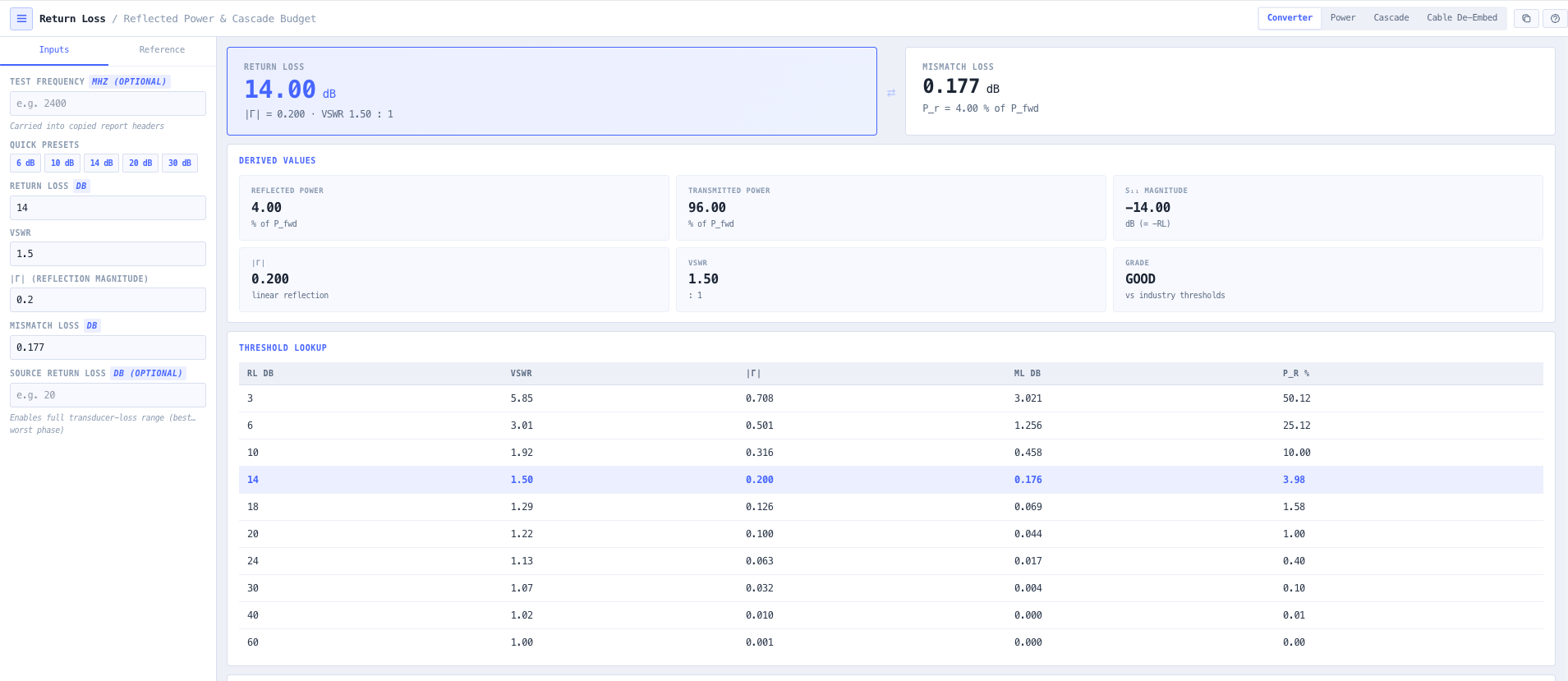
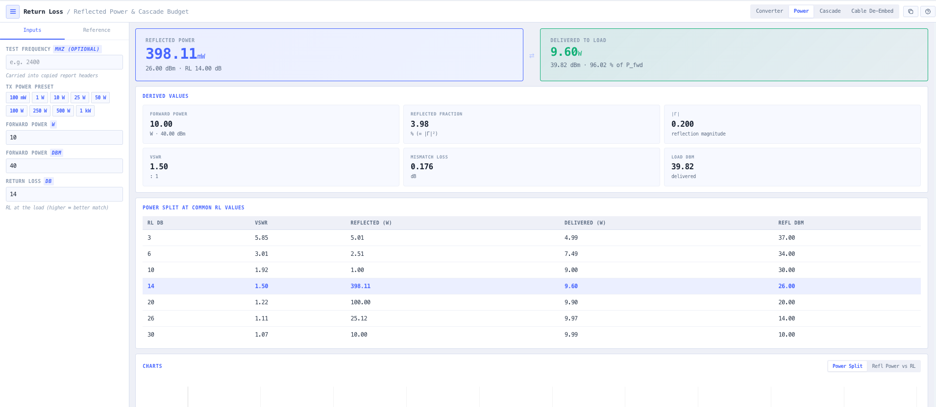
Return loss is the everyday metric of RF installation and commissioning. Antenna analysers, vector network analysers, and field test sets all report it directly, and contractual specifications, vendor datasheets, and licence conditions are routinely written in dB of return loss. The relationship to reflected power is direct but not obvious without a calculator. A 14 dB return loss leaves about 4 per cent of forward power reflected. A 20 dB return loss leaves 1 per cent. A 10 dB return loss leaves 10 per cent. For high power transmitters, that fraction matters in absolute watts (a 1 kilowatt transmitter feeding a 14 dB return loss antenna has 40 watts of reflected power circulating in the feed system, which is enough to damage circulators, duplexers, and arrestors that were not sized for it).

The noIM₃ Return Loss Calculator handles every adjacent quantity in one workspace. Bidirectional conversion between return loss, VSWR, magnitude Gamma, and mismatch loss with reflected and transmitted power percentages, all updating simultaneously so a number from any source translates instantly to every other form. Forward power input in watts or dBm (converted live between the two) returns reflected power and the power delivered to the load in both watts and dBm, auto-scaled to milliwatts, microwatts, or kilowatts for readability. Useful for high power transmitter safety analysis and for protecting downstream components from circulating reflected energy.

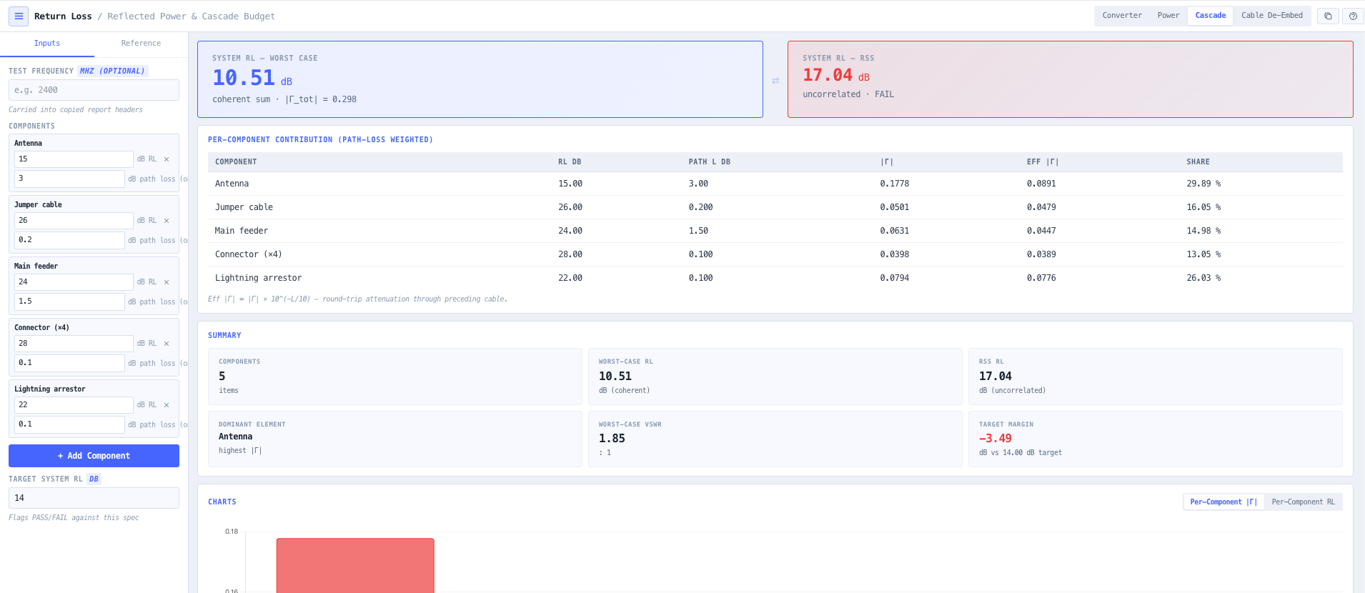
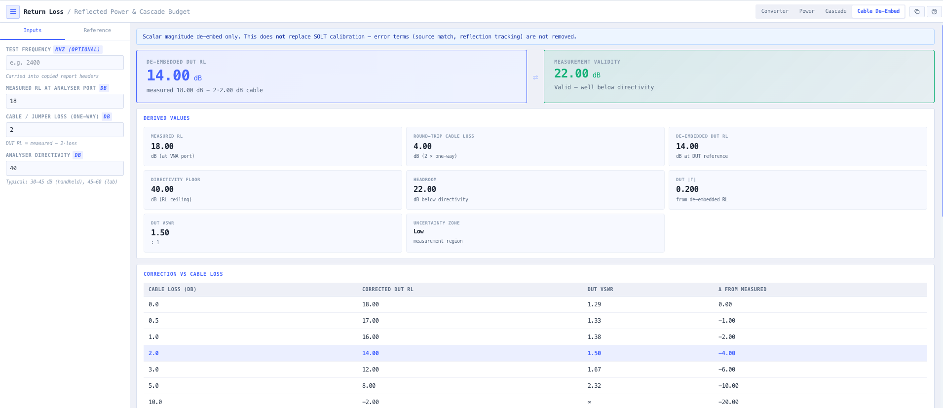
Beyond conversion, the calculator covers the cascade and measurement workflows engineers actually need. Cascade return loss budget rolls up the contributions of a free-text named component list (antenna, jumper cable, main feeder, connectors, lightning arrestor), each weighted by the round-trip loss of the feeder run in front of it so a reflection behind a lossy feeder counts for less, and reports both worst case coherent (all reflections in phase) and root sum of squares (uncorrelated) system return loss, with a per component bar chart that identifies which element dominates the system mismatch. Vector network analyser correction handles the case where the analyser is at the bottom of a tower or behind a long jumper run. True DUT return loss equals measured return loss minus 2 times cable loss in dB. Directivity floor warning fires when the DUT return loss approaches the analyser directivity, flagging the measurement noise limited region where readings are not trustworthy.

Capabilities

Return loss to VSWR to magnitude Gamma to mismatch loss conversion

Edit any of return loss in dB, VSWR, magnitude Gamma, or mismatch loss in dB and the others update instantly. Reflected power and transmitted power percentages surfaced alongside, so a number on a datasheet or analyser trace translates directly into what proportion of the incident wave reaches the load. Useful for cross referencing measurements between instruments and specifications.

Reflected power in watts and dBm

Forward power input in watts or dBm, converted live between the two. Output covers reflected power (P forward times magnitude Gamma squared) and the power delivered to the load, both in watts and dBm and auto-scaled to milliwatts, microwatts, or kilowatts. Essential for high power transmitter safety analysis, for protecting circulators and duplexers from circulating reflected energy, and for sizing surge protection and lightning arrestor power ratings.

Cascade return loss budget

Roll up the return loss contributions of a free-text named component list, each row carrying its own return loss and the one-way loss of the feeder run in front of it, so a reflection behind a lossy feeder is weighted down by the round trip. Reports worst case coherent return loss (all reflections in phase) and root sum of squares return loss (uncorrelated). Worst case coherent is the conservative budget for high reliability designs. RSS is the typical case. The calculator surfaces both so the design discussion can target either bound.

Per component contribution bar chart

Bar chart showing the magnitude Gamma contribution of each cascade element, sorted from largest to smallest. Identifies which element dominates the system mismatch so remediation effort targets the actual bottleneck rather than the cosmetic ones. Useful for tower top installations where multiple components contribute and the question is which one to upgrade first.

Vector network analyser correction

Corrects an apparent return loss measured through a lossy feeder. True DUT return loss equals measured return loss minus 2 times cable loss in dB (the factor of 2 because the reflected wave traverses the cable twice). Useful when the analyser is at the bottom of a tower with a long jumper to the antenna under test, or when the device under test is behind a length of feeder.

Directivity floor warning

Reports the analyser directivity floor (typically 30 to 40 dB depending on instrument quality) and flags when the device under test return loss approaches the floor. Measurements in this noise limited region are not trustworthy. The warning prevents engineers from reporting an artefact return loss as a real measurement and supports correct interpretation of high return loss readings.

Reference threshold lookup table

Built in conversion table covering common return loss values (3, 6, 10, 14, 20, 30, 40 dB) with the corresponding VSWR, magnitude Gamma, mismatch loss in dB, and reflected power percentage. Useful as a quick reference during design discussions and for engineers learning the relationships.

Transmitter power presets

Built in presets for typical transmitter output levels (100 mW, 1 W, 10 W, 25 W, 50 W, 100 W, 250 W, 500 W, and 1 kW). Each preset populates the forward power so reflected power calculations are one click for common deployment scenarios.

Browser only computation

Runs entirely in your browser. No measurement values, transmitter power levels, or design data are submitted to a server. Useful for commercially confidential RF installation work, defence and intelligence sites, and environments where information security policy prohibits sending engineering data to third party services.

Standards & methodology

  • IEEE 145. Standard definitions of terms for antennas
  • IEEE 287. Precision coaxial connectors
  • 50 ohm reference impedance for RF systems
  • Vector network analyser directivity convention (typical 30 to 40 dB)
  • Cascade reflection coefficient summation rules (worst case coherent and RSS)

When to use this tool

  • Antenna and feeder commissioning measurements
  • Transmitter, duplexer, circulator, and arrestor safety analysis through reflected power budgeting
  • System level return loss roll up across multi component installations
  • Vector network analyser S11 reading correction for cable loss and directivity floor
  • Datasheet interpretation (return loss to VSWR to mismatch loss conversion)
  • Distributed antenna system and tower top equipment acceptance testing
  • Training and educational visualisation of return loss and reflected power
  • High power broadcast transmitter feed system safety design
  • Lightning arrestor and surge suppressor return loss budget allocation
  • Identifying the dominant return loss contributor in a complex feed system
  • Producing return loss evidence for ACMA radiocommunications licence applications
  • Validating contractual return loss specifications during installation acceptance

Is this the right tool for you?

Reach for the Return Loss Calculator in any of the following situations.

  • You are commissioning a new antenna installation and want to convert measured return loss into VSWR for the acceptance test report against a contractual specification.
  • You are responsible for a high power broadcast or transmitter installation and need to calculate reflected power in watts to size the duplexer and arrestor power handling.
  • You are reading a vector network analyser screen at the bottom of a tower and need to subtract cable loss from the measured return loss to recover the true antenna return loss.
  • You are diagnosing a feed system where the measured return loss is approaching the analyser directivity floor and need to confirm whether the result is genuine or measurement noise.
  • You are doing a system level return loss roll up across antenna, jumper, main feeder, connector, and arrestor and need both the worst case coherent and RSS budget.
  • You are identifying which component in a multi element tower top installation is dominating the system return loss before approving a remediation visit.
  • You are checking that a lightning arrestor or surge suppressor with a quoted return loss does not push the system below the specification.
  • You are responsible for transmitter safety design and need to confirm reflected power into the circulator stays within the manufacturer specified maximum.
  • You are validating a contractual return loss specification (for example better than 14 dB across the operating band) during installation acceptance.
  • You are interpreting an antenna datasheet that quotes return loss and need the equivalent VSWR for cross reference against your test equipment.
  • You are responsible for a distributed antenna system or in building cellular installation and need return loss evidence per cable run and per radiating element.
  • You are training new RF technicians in return loss interpretation and want a teaching tool that shows the relationships between return loss, VSWR, mismatch loss, and reflected power side by side.
  • You are producing return loss evidence for an ACMA radiocommunications licence application that requires documented antenna and feed system performance.
  • You are responsible for an emergency or safety critical radio installation and need defensible return loss budgeting against worst case conditions.
  • You are operating under a security regime that prohibits sending measurement data to third party services and need a return loss calculator that runs entirely in your browser.

Frequently asked questions

How is return loss converted to other quantities?

Return loss in dB equals minus 20 log of magnitude Gamma. Magnitude Gamma equals 10 to the minus return loss over 20. VSWR equals (1 plus magnitude Gamma) divided by (1 minus magnitude Gamma). Mismatch loss equals minus 10 log of (1 minus magnitude Gamma squared). Reflected power equals forward power times magnitude Gamma squared (or equivalently forward power times 10 to the minus return loss over 10). Edit any of these and the others update simultaneously.

Why does return loss matter for high power transmitters?

Even small reflections from a high power transmitter produce significant absolute reflected power. A 1 kilowatt transmitter feeding a 14 dB return loss antenna (about 4 per cent reflected) produces 40 watts of reflected power circulating in the feed system. This is enough to overheat circulators, duplexers, and arrestors that were not specified for it, or to fold back transmitter output power through protection circuits. The calculator returns reflected power in watts directly so safety margins against component ratings are visible.

How does the cascade budget work?

Multiple components in series each contribute to the system reflection. Each component reflection is first weighted by the round-trip loss of the feeder run in front of it (10 to the minus path loss over 10), so a mismatch behind a lossy feeder counts for less at the source. Worst case coherent return loss then assumes all reflections add in phase, which is the conservative bound. The weighted magnitudes add directly, magnitude Gamma worst equals sum of the weighted magnitude Gamma i. Root sum of squares assumes the reflections are uncorrelated, which is the typical case in real installations. magnitude Gamma RSS equals square root of (sum of the weighted magnitude Gamma i squared). The calculator returns both bounds so the design discussion can target either.

How does VNA cable loss correction work?

When the network analyser measures through a length of feeder, the reflected wave traverses the cable twice on its way back to the analyser, so the apparent return loss reads better than the true device under test return loss by twice the one way cable loss. True DUT return loss equals measured return loss minus 2 times cable loss in dB. The calculator handles this directly given the cable loss value, which is the standard correction during tower top antenna commissioning where the analyser sits at the base.

What is the directivity floor and why does it matter?

Vector network analyser directivity is the residual reflection inside the analyser itself, typically 30 to 40 dB depending on instrument quality. When the device under test return loss is much better than the directivity floor, the analyser is reading its own internal reflection rather than the DUT, which produces measurement artefacts that look like real return loss readings. The calculator flags this region and prevents engineers from reporting artefact data as a real measurement.

How does this differ from the VSWR and Reflection Coefficient calculators?

The VSWR Calculator focuses on quick conversion between forward and reflected power, VSWR, return loss, and mismatch loss as scalar quantities, with quality presets for system health assessment. The Reflection Coefficient Calculator covers full complex Gamma analysis including impedance recovery and frequency sweep modelling for matching network design. The Return Loss Calculator extends those with the cascade budget, reflected power in watts, VNA correction, and the workflows specific to installation, commissioning, and safety analysis. Use VSWR for fast bench, Reflection Coefficient for matching design, and Return Loss for installation and commissioning work.

What return loss should I aim for in a typical installation?

Industry typical specifications are 14 to 15 dB return loss for cellular and broadcast antennas (corresponding to about VSWR 1.5 to 1). 20 dB or better for high quality production antennas (about VSWR 1.2 to 1). 30 dB or better for laboratory and precision applications. 10 dB is the practical line above which the link behaves acceptably for most applications. Below 10 dB return loss the reflected power becomes a meaningful fraction of forward and the link is degraded.

Does any data leave my browser?

No. The calculator runs entirely in your browser. No measurement values, transmitter power levels, or design data are submitted to a server. Useful for commercially confidential RF installation work, defence and intelligence sites, and environments where information security policy prohibits sending engineering data to third party services.