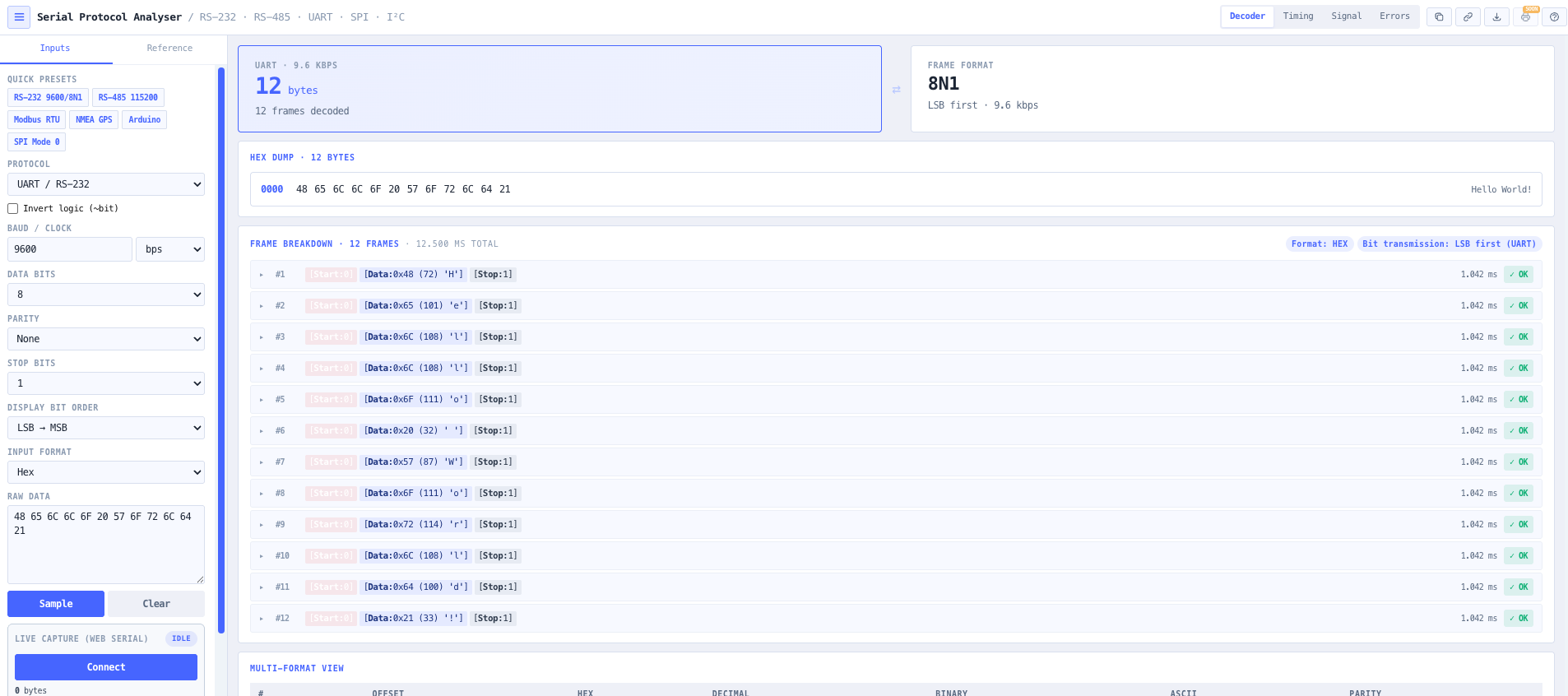
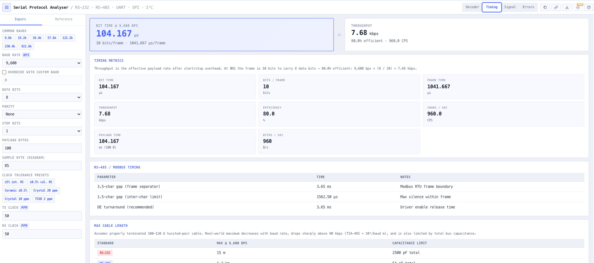
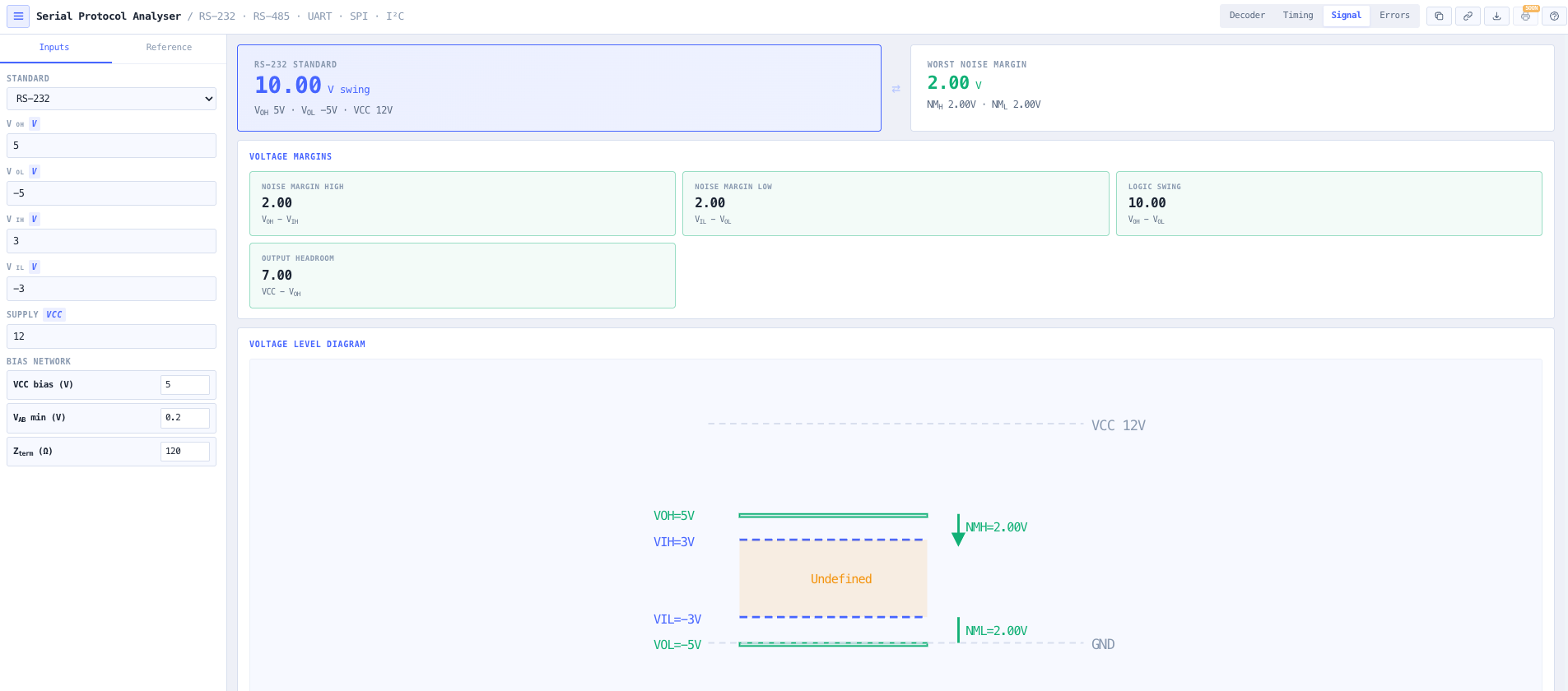
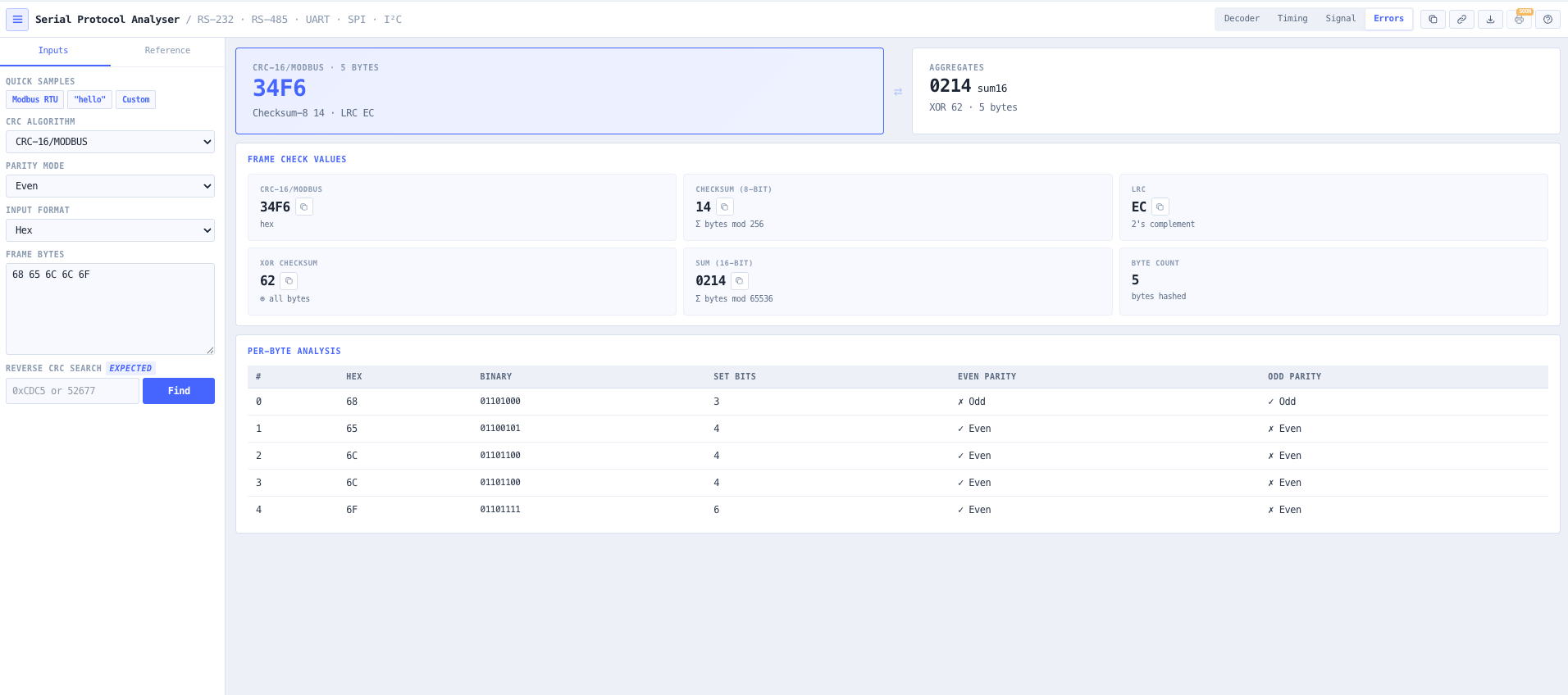
Browser native protocol analyser for RS-232, RS-485, RS-422, UART, SPI, I²C, CAN / J1939, DMX-512, and M-Bus. Live capture over Web Serial, Saleae and Logic 2 CSV import, full Modbus RTU interpretation with exception and register decode, timing and clock tolerance analysis, RS-485 unit load and bias network checks, and CRC reverse search.
Top bar with the four analyser modes — Decoder, Timing, Signal, Errors.
Overview
What the Serial Protocol Analyser does
Serial communication is where most field commissioning time disappears. The radio is fine. The PLC is fine. The cable is fine. But the Modbus master returns an exception 02 on a register the vendor documentation insists exists, the RS-485 segment drops every fifth poll on a long cable run, the SCADA tag stays at the default value because the byte order in the register is reversed, and nobody on site can prove which side of the link is at fault. The protocol analyser is the one tool that closes the argument: it shows the wire, decodes the frames, and verifies the integrity of every byte against the protocol specification.
Read the full overview
The noIM₃ Serial Protocol Analyser brings a commissioning grade serial analyser into the browser. Four modes share one workspace. The Decoder mode parses UART, RS-485 / RS-422, SPI, I²C, CAN / J1939, DMX-512, and M-Bus frames from a live Web Serial capture, a Saleae or Logic 2 CSV import, or a pasted byte stream. The Timing mode validates a baud generator divisor against TX and RX clock tolerance, computes the bit time, frame time, throughput, and efficiency for the configured frame format, and surfaces the safety margin against the maximum tolerable mismatch. The Signal mode handles the electrical side: RS-232, RS-485, RS-422, TTL, LVTTL, and LVCMOS noise margin (V_OH minus V_IH and V_IL minus V_OL), RS-485 differential threshold, TIA-485 unit load compliance for 1 / ½ / ¼ / ⅛ UL devices, and bias network voltage at the idle bus. The Errors mode runs the captured bytes through every CRC algorithm in the catalogue (CRC-16/Modbus, CRC-16/CCITT, CRC-32/Ethernet, CRC-8/Maxim, and more), checksum-8, LRC, XOR, sum-16, and supports a reverse CRC search to identify which algorithm a vendor device is actually using when documentation is wrong.
Live capture is the headline feature. With a Chromium based browser on an HTTPS origin (or localhost), the Connect button opens the browser native port picker, opens the selected USB serial adapter at the configured protocol settings, and streams bytes into the decoder in real time. Bytes accumulate into the rawInput pane, the live decode pipeline runs against every chunk as it arrives, and a one click Send to decoder button hands the captured stream to the Modbus / NMEA / MAVLink interpreters. CSV import covers the offline path: a Saleae Logic 2 export with `time, value` columns or an async serial digital channel export is parsed, framing and parity errors are flagged inline, and the same downstream interpretation runs on the imported bytes. Outputs include a hex / decimal / binary / ASCII byte table, a per frame breakdown with bit level diagrams for UART and RS-485, and a Modbus RTU panel that distinguishes query / response / exception roles and renders register and coil tables for FC 1 to 4 responses with exception reason text for codes 01 to 0B.
Capabilities 10
Live capture via Web Serial
The Connect button opens the Chromium native port picker, opens the selected USB serial adapter (or Bluetooth serial profile) at the configured protocol settings, and streams bytes into the decoder in real time. Live decode runs against every chunk so the Modbus / NMEA / MAVLink interpretation updates as bytes arrive. The browser remembers granted ports per origin so reconnecting is one click. Requires Chrome, Edge, or Opera served over HTTPS (or localhost); Firefox and Safari fall back to CSV import and paste workflows.
Multi protocol decode
UART / RS-232, RS-485 / RS-422, SPI (CPOL / CPHA modes 0 to 3), I²C (Standard, Fast, Fast-Plus, High-Speed, 7 and 10 bit address), CAN / J1939 (PGN catalogue and frame parser), DMX-512 (E1.11), and M-Bus (EN 13757). Each protocol has the correct frame ordering (UART start / data / parity / stop with LSB first transmission and MSB or LSB display), the right wire convention, and the right inter character / inter frame gap interpretation. Inverted logic (idle / active polarity flip) is a one click toggle for TTL probes on RS-232 lines and vice versa.
Modbus RTU interpretation with role detection
The Modbus panel distinguishes query, response, and exception roles based on the function code and the payload shape. FC 1 and 2 responses are decoded into a coil bit grid; FC 3 and 4 responses are decoded into a register table with unsigned, signed (i16), hexadecimal, and binary columns; FC 5 and 6 write commands surface the target coil or register and the written value (with validation that FC 5 writes 0x0000 or 0xFF00). Broadcast addressing (slave 0) is flagged inline. Exception responses (FC | 0x80) are decoded into the exception code, the name (Illegal Function, Illegal Data Address, etc.), and a plain language reason that names the likely cause on site rather than just the code.
Saleae and Logic 2 CSV import
A CSV exported from a USB logic analyser (Saleae Logic 2, or another capture tool that produces `time, value` columns or an async serial digital channel export) is parsed in the browser. Hex (0x48) and decimal (72) value formats are both accepted. Framing and parity errors detected during the import are flagged inline against the affected bytes, and per byte timestamps are preserved so the downstream decoder can show inter character gaps. The same downstream interpretation runs on imported bytes as on live captured bytes.
Timing analysis with clock tolerance
Validates a baud generator divisor against TX and RX clock tolerance (parts per million). Computes the bit time, the frame time, throughput in kbps, and frame efficiency (data bits divided by frame bits). Common oscillator presets (XTAL, ceramic resonator, MEMS, RC oscillator) populate ppm values for fast sanity checks against the maximum tolerable mismatch (typically 3 percent for an 8 bit UART frame). Surfaces the safety margin so a borderline RS-485 link over a low cost RC oscillator is identified before it fails on site.
RS-485 electrical and bus loading analysis
Signal mode handles RS-485, RS-422, RS-232, TTL, LVTTL, and LVCMOS. Calculates V_OH minus V_IH and V_IL minus V_OL noise margins, RS-485 differential threshold, the differential signal swing, and the common mode range. TIA-485 unit load compliance is checked against 1 UL, ½ UL, ¼ UL, and ⅛ UL devices on the bus (limit 32 UL). The bias network solver returns the fail-safe pull-up and pull-down resistor values needed to keep V_AB above the 200 mV differential threshold at the idle bus, taking V_CC, termination, and bus load into account.
CRC catalogue and reverse search
The errors mode runs the captured bytes through every algorithm in the CRC catalogue: CRC-8/Maxim, CRC-8/J1850, CRC-16/Modbus, CRC-16/CCITT, CRC-16/XMODEM, CRC-32/Ethernet, CRC-32/Castagnoli, and more, plus checksum-8, LRC, XOR, and sum-16. A reverse CRC search takes an expected CRC value (the value a vendor device returned for a known frame) and identifies which algorithm matches, finally closing the argument when documentation says one thing and the device does another.
NMEA-0183 and MAVLink detection
NMEA-0183 sentences ($TTSSS,...*HH) embedded anywhere in the byte stream are extracted, the talker (GP for GPS, GN for multi-GNSS, etc.) and sentence (GGA, RMC, GSV, etc.) are decoded, and the XOR checksum is verified. MAVLink v1 (0xFE magic) and v2 (0xFD magic, 24 bit message ID, optional 13 byte signature) frames are detected and their headers parsed. Useful for marine, automation, and UAV integration work where serial captures often contain mixed protocol traffic.
Decoder presets and quick samples
One click presets for the common configurations: RS-232 9600 8N1, RS-485 115200, Modbus RTU at 9600 8E1, NMEA GPS at 4800, Arduino 115200, SPI Mode 0. Sample data buttons load known good frames (a Modbus FC 3 request, the ASCII string "hello", and a synthetic frame) so the analyser can be evaluated immediately without a live capture or a CSV import.
Browser only computation
Runs entirely in your browser. Captured bytes, imported CSV files, and decoded frames are not submitted to any server. Useful for commercially confidential infrastructure work, OT / SCADA networks under air gap policy, and any environment where information security policy prohibits sending engineering data to third party services.
Baud rate or clock frequency (300 bps to 10 Mbps, with kbps and Mbps unit selection)
Frame format: data bits (5 to 9), parity (None, Even, Odd, Mark, Space), stop bits (1, 1.5, 2)
SPI mode (CPOL / CPHA) and word size (8 or 16 bit)
I²C speed mode (Standard, Fast, Fast-Plus, High-Speed) and address bits (7 or 10)
Inverted logic toggle (simulate captured signal with reversed polarity)
Input format (Hex, Binary, ASCII, Decimal) for pasted byte data
Live Web Serial capture via the browser port picker (one click connect + start)
Saleae and Logic 2 CSV import (time + value columns or async serial digital channel export)
Signal standard for electrical analysis (RS-232, RS-485, RS-422, TTL, LVTTL 3.3V, LVCMOS 1.8V)
V_OH, V_OL, V_IH, V_IL, V_CC, differential threshold for the signal mode
RS-485 bus loading: number of 1 / ½ / ¼ / ⅛ UL devices, V_CC, V_AB minimum, termination impedance
Timing mode: payload bytes, sample byte for diagram, oscillator preset, TX and RX ppm clock tolerance
Errors mode: CRC algorithm from the catalogue, parity mode, frame bytes, optional expected CRC for reverse search
Outputs 15
Hex / decimal / binary / ASCII byte table with parity flag and per byte framing / parity error indicators
Per frame breakdown with bit level diagram (UART / RS-485) showing start, data, parity, and stop bits
Modbus RTU interpretation: role (query / response / exception), slave ID with broadcast flag, function code, function name, payload interpretation, CRC received vs computed, CRC verdict
Modbus register table (offset, hex, unsigned, signed i16, binary) for FC 3 and 4 responses
Modbus coil bit grid for FC 1 and 2 responses
Modbus exception text (code, name, plain language reason) for exception responses (FC | 0x80)
NMEA-0183 sentence list with talker, sentence type, fields, and checksum verdict
MAVLink v1 / v2 frame breakdown (version, payload length, sequence, system ID, component ID, message ID, signed flag for v2)
CAN / J1939 frame parse with PGN catalogue lookup
DMX-512 universe decode with start code and channel data
M-Bus telemetry decode per EN 13757
Timing: bit time (µs), frame time (µs), throughput (kbps), efficiency (%), safety margin against the maximum tolerable mismatch
Signal: V_OH minus V_IH and V_IL minus V_OL noise margins, swing, common mode range, RS-485 differential threshold compliance, TIA-485 unit load compliance, bias network resistor values
Errors: CRC value for every algorithm in the catalogue, checksum-8, LRC, XOR, sum-16, reverse CRC search results
JSON export of the decoded frames with the protocol configuration and the raw bytes
Standards & methodology
TIA / EIA-232-F (RS-232) electrical and signalling standard
TIA / EIA-485-A (RS-485) differential signalling standard with unit load and bias network conventions
TIA / EIA-422-B (RS-422) differential signalling standard
Modbus RTU Application Protocol V1.1b3 and Modbus Serial Line Protocol V1.02
Live capture uses the Web Serial API, which is supported on Chromium based browsers (Chrome, Edge, Opera) served over HTTPS or localhost. Firefox and Safari do not currently implement Web Serial; on those browsers the live capture panel is disabled and the analyser falls back to the CSV import and paste workflows. The Web Serial spec requires a user gesture (a click) to open the port picker, so the Connect button must be clicked rather than triggered programmatically.
What protocols can the analyser decode?
UART / RS-232, RS-485 / RS-422 (Modbus RTU), SPI (CPOL / CPHA modes 0 to 3), I²C (Standard, Fast, Fast-Plus, High-Speed, 7 and 10 bit address), CAN / J1939 with the PGN catalogue, DMX-512 per ANSI E1.11, and M-Bus per EN 13757. NMEA-0183 sentences and MAVLink v1 / v2 frames are detected automatically anywhere they appear in the byte stream, so a mixed traffic capture can be decoded without manually splitting the protocols.
How does the Modbus interpretation handle response frames?
The decoder looks at the function code and the payload shape and infers the role: query, response, or exception. A 4 byte payload after FC 1 to 4 is a query (start address + quantity). A payload where the first byte equals the byte count and the rest matches the documented response shape is a response: FC 1 and 2 are decoded into a coil bit grid, FC 3 and 4 are decoded into a register table with unsigned, signed (i16), hexadecimal, and binary columns. Exception responses (FC | 0x80) decode to the exception code, name, and a plain language reason for codes 01 through 0B. Broadcast addressing (slave 0) is flagged inline because broadcast frames receive no response.
What CRC algorithms are in the catalogue?
CRC-8/Maxim (1-Wire), CRC-8/J1850, CRC-16/Modbus, CRC-16/CCITT (XMODEM and FALSE), CRC-16/XMODEM, CRC-16/USB, CRC-16/DNP, CRC-32/Ethernet, CRC-32/Castagnoli, and more — each with the documented polynomial, initial value, reflection settings, and final XOR. The reverse CRC search takes an expected CRC value and runs the captured frame through every catalogue algorithm to identify which one matches, which is the fastest way to identify the integrity check on a vendor protocol when documentation is silent.
Can I import a Saleae Logic 2 CSV?
Yes. The CSV import accepts either a `time, value` two column export or a Saleae async serial digital channel export. Both hex (0x48) and decimal (72) value formats are accepted. Per byte timestamps are preserved through the decoder so the byte table can display the actual capture time of every byte; framing and parity errors flagged during the import are surfaced inline against the affected bytes so the operator can see which captured byte caused the decode failure.
Is the captured data uploaded to a server?
No. All decoding, all CRC computation, and all Web Serial capture runs entirely in your browser. The captured byte stream, the imported CSV file, and the decoded frames are never uploaded to a server. This is important for OT / SCADA environments under air gap policy and for commercially confidential infrastructure work.
Does it work for SPI and I²C captured from a logic analyser?
Yes. SPI mode handles the four CPOL / CPHA combinations (modes 0 through 3) with 8 or 16 bit word sizes. I²C mode handles the standard speed modes (100 kHz Standard, 400 kHz Fast, 1 MHz Fast-Plus, 3.4 MHz High-Speed) with 7 or 10 bit addressing. Both protocols expect a logic analyser export with the captured bytes; the analyser interprets the byte stream against the configured mode.