Frequency Coordination

Frequency Plan Validator

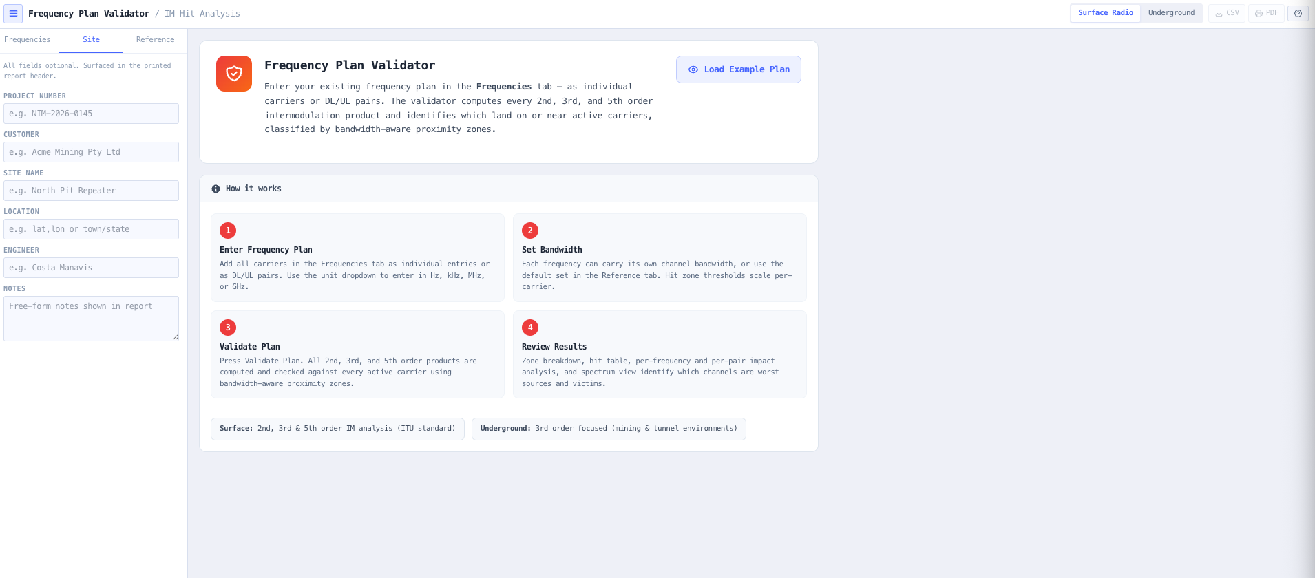
Audit any existing radio frequency plan for intermodulation hits. Bandwidth aware proximity classification across 2nd, 3rd, and 5th order products, graded to ITU-R SM.1134-1, ACMA RALI LM 08 Table D2 or a custom separation, with no plan changes required.

Included in the 14-day Pro trial on every new account. No credit card.

Overview

Most radio sites in operation today were not designed dirty. They became dirty over time as channels were added, splits were adjusted, and incumbents moved into adjacent spectrum. The radios still key, the audio still passes, but range shortens, weak users drop out, and intermittent in band interference starts showing up in complaints. Before anyone reaches for new antennas, new repeaters, or a full redesign, the right first question is simpler. Is the existing frequency plan generating intermodulation interference, and if so, where?

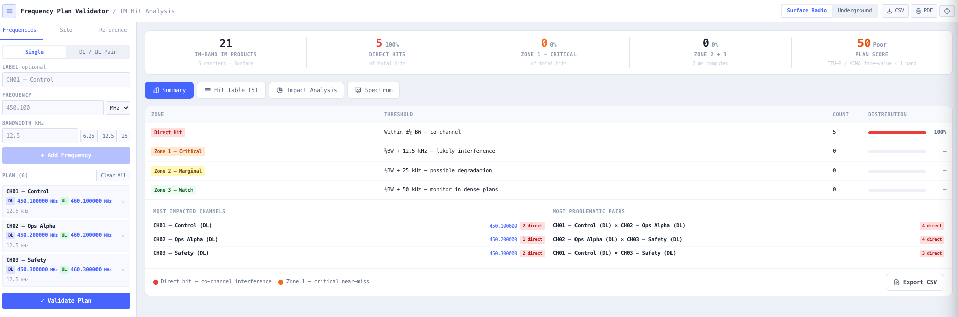
The noIM₃ Frequency Plan Validator answers exactly that question. Submit your current channel list and the engine evaluates every frequency combination for 2nd, 3rd, and 5th order products in surface mode, or 2nd and 3rd order in underground mode, where 5th order is omitted. Each product is then checked against every active carrier using a bandwidth aware proximity model, so a 100 kHz wideband channel has proportionally wider hit zones than a 12.5 kHz narrowband channel. The Direct boundary is a cited rule you choose: ITU-R SM.1134-1 (plus or minus half the channel bandwidth), ACMA RALI LM 08 Annex D Table D2 for surface plans, or a custom separation such as the one a coordination request was planned to, and the report names which rule was used and how a product exactly on the boundary was read.

Output is a complete intermodulation audit. A zone breakdown table classifies each hit as direct, critical near, marginal, or watch. A sortable hit table shows the offending intermodulation frequency, the order, the full formula, the contributor channels, the target channel, and the separation in kHz. A frequency impact analysis shows which channels are the worst sources and the most affected victims. A pair interaction table identifies the most dangerous combinations. A spectrum view renders carriers as spikes and overlays direct hits in red. Computation runs entirely in your browser. No data leaves your machine.

Capabilities

Bandwidth aware hit zone classification

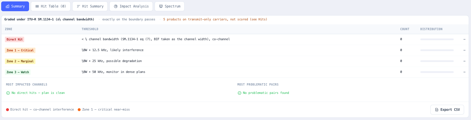
Each hit is classified by proximity to the target carrier, scaled against that carrier bandwidth. Direct hit means the intermodulation product falls within plus or minus half the channel bandwidth (co channel, in band interference), the criterion of ITU-R SM.1134-1 section 3.1. Zone 1 (critical near) extends from half BW to half BW plus 12.5 kHz. Zone 2 (marginal) covers half BW plus 12.5 to 25 kHz. Zone 3 (watch) covers half BW plus 25 to 50 kHz. Zones scale per carrier, so a 100 kHz channel has a much wider direct hit zone than a 12.5 kHz channel. Surface plans can be graded to ACMA RALI LM 08 Annex D Table D2 instead, where the hit range is read by interferer width, receiver width and order, or to a custom separation; the report names which rule was used and how a product exactly on the boundary was read.

Surface and underground analysis

Surface mode evaluates 2nd, 3rd, and 5th order products typical of open air systems, with ITU-R SM.1134 carrier roles, so a product landing on a transmit-only carrier is listed as a transmit landing rather than scored as a hit. Underground mode evaluates 2nd and 3rd order and omits 5th order, disables the transmit to receive pair isolation because the leaky feeder cable brings TX and RX into the same level range, and lets you choose whether downlink and uplink carriers are combined with each other.

Full hit table with formulae and contributors

Every intermodulation product that falls within any proximity zone is recorded as a row. Intermodulation frequency, order, full formula, contributor channel labels, target channel, separation in kHz, the Direct boundary the hit was graded against, zone classification, predicted level at the victim and margin above noise. Sorted by severity, direct hits first, then by increasing separation. A hit summary view groups the carriers by downlink, uplink and unpaired leg and counts the products on each centre frequency and inside each channel. Exportable as CSV for inclusion in interference reports or client deliverables.

Frequency impact analysis

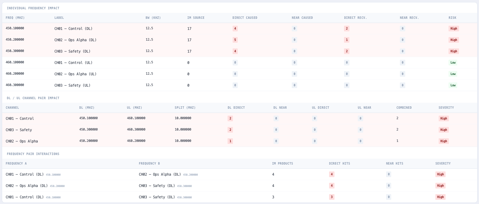
Two impact tables break the problem down by channel. The per frequency table shows each channel as both source (how many products it contributes to and how many direct or near hits it causes) and victim (how many direct and near hits land on it). Channels are colour coded by risk level. The pair interaction table identifies which frequency pairs generate the most hits when combined.

Spectrum view with direct hit highlighting

All carriers render as vertical spikes with bandwidth shading. Every in band intermodulation product is overlaid. Direct hits are drawn in red on top of the carrier spike, making problematic channels immediately obvious. Near miss products appear as blue markers between carriers. Colour coding matches the zone classification system used throughout the tool.

Most impacted channels and most problematic pairs

Headline summaries surface the worst victim channels and the most dangerous source pairs at the top of the result. Useful for prioritising which channels to investigate first when remediation effort is constrained, and for justifying which pairs to separate in a follow on optimisation pass.

CSV export and report ready output

The full hit table exports as CSV ready to drop into an interference report, a regulatory submission, or a client deliverable, opening with a preamble that names the hit criterion, the boundary reading, any custom separation and the products not assessed. The long form PDF report carries the same, with the site metadata, parameters, summary, hit table, transmit landings, impact tables and spectrum plot. Both preserve every formula, zone and contributor label, so the export is reviewable line by line by another engineer rather than being a black box.

Projects that follow your account

Computation runs in your browser; no carrier list is sent anywhere to be analysed. Each plan is a project that autosaves as you work, mirrors to your noIM3 account so it follows you across devices, and imports and exports as a .fpv.json file that keeps the carriers, the criterion, the zone thresholds and the model settings, so a reopened plan validates to the same numbers it did when it was saved. A Frequency Coordination or Frequency Plan Optimiser result opens here in one click, already set to the separation it was planned to.

Standards & methodology

  • ITU-R SM.1134-1 section 3.1. Direct hit within half the channel bandwidth (default criterion)
  • ACMA RALI LM 08 section 6.5.3 and Annex D Table D2. Hit range by interferer width, receiver width and order (surface plans)
  • ITU SM.1446. Intermodulation interference reference
  • ITU SM.337. Frequency separation between adjacent transmissions
  • ACMA spectrum management framework alignment for Australian deployments

When to use this tool

  • Auditing a brownfield radio system before a planned maintenance shutdown
  • Reviewing a vendor or consultant proposed greenfield plan before acceptance
  • Identifying which channels are causing interference complaints in an operational system
  • Validating a new channel addition to an existing plan before programming radios
  • Producing an intermodulation audit report for a client or regulatory submission
  • Comparing surface and underground analysis assumptions for a mine site plan
  • Prioritising frequency coordination work by surfacing the worst source pairs
  • Confirming a plan is clean before deploying into a congested spectrum environment
  • Supporting ACMA licence renewal or variation with documented intermodulation evidence
  • Investigating intermittent in band interference reports without modifying the plan
  • Preparing the input for a follow on Frequency Plan Optimiser run
  • Teaching new RF engineers how intermodulation products land on real channel plans

Frequently asked questions

How is this different from the Frequency Plan Optimiser?

The validator audits an existing plan and reports where intermodulation hits land, without changing anything. The optimiser takes the same input and proposes precision channel shifts to clean it up. Use the validator first to baseline the problem and produce evidence. Use the optimiser to actually fix it, then open its result here in one click: it arrives at the separation it was solved to, with the same product set, so the two agree on what a hit is.

What does bandwidth aware proximity actually mean?

Hit zone thresholds scale with each individual channel bandwidth rather than a fixed value across the plan. A 100 kHz wideband channel has a direct hit zone of plus or minus 50 kHz. A 12.5 kHz narrowband channel has a direct hit zone of plus or minus 6.25 kHz. The result is that mixed bandwidth plans get a fair audit rather than every wideband channel being flagged or every narrowband channel being missed.

Which intermodulation orders are evaluated?

In surface mode, 2nd order (fg plus or minus fh), 3rd order two signal (2fg minus fh) and three signal (fg plus fh minus fm), and 5th order two signal and three signal products are evaluated. Underground mode evaluates 2nd order and both 3rd order families and omits 5th order: the 5th order three signal family is effectively un-plannable, and the two signal product sits below the noise floor once leaky feeder coupling loss and cascade amplifier IM rejection are counted.

Does any frequency data leave my browser?

Not for analysis. Computation runs entirely in your browser and no carrier list is sent anywhere to be validated. Your projects are saved locally and mirrored to your noIM3 account so they follow you across devices; if a plan must stay off the account, export it as a .fpv.json file and delete the project.

What does the CSV export contain?

A preamble naming the hit criterion, the boundary reading, any custom separation and the number of products not assessed, then one row per hit with intermodulation frequency, order, full formula, contributor channel labels, target channel, separation in kHz, the Direct boundary it was graded against, zone classification, predicted level and margin above noise, followed by the transmit landings labelled as such. Sorted by severity. Suitable for inclusion in interference reports, client deliverables, or as the input record for a follow on optimisation pass.

Can I use this on a greenfield plan before deployment?

Yes. The validator does not care whether the plan is operational or proposed. Submit a candidate plan and you get the same intermodulation audit. Useful for confirming a vendor or consultant submitted plan is actually clean before you accept it, or for sanity checking your own greenfield design before programming radios.

How are direct, critical near, marginal, and watch zones defined?

Direct is within the chosen boundary: plus or minus half the channel bandwidth under ITU-R SM.1134-1 (the default), the Table D2 offset under RALI LM 08, or the custom separation. Zone 1 critical near extends from the boundary to the boundary plus 12.5 kHz. Zone 2 marginal covers the boundary plus 12.5 to 25 kHz. Zone 3 watch covers the boundary plus 25 to 50 kHz. Each zone has a distinct colour throughout the table, summary, and spectrum view.

Which hit criterion should I use?

ITU-R SM.1134-1, plus or minus half the channel bandwidth, is the default and matches the Intermodulation Calculator. ACMA RALI LM 08 Table D2 is the rule the frequency assignment process applies to surface land mobile plans: the hit range is read by interferer width, receiver width and order, and is wider, plus or minus 18 kHz for a 12.5 kHz interferer into a 12.5 kHz receiver, so a plan that is clean at half bandwidth can carry LM 08 hits. Table D2 covers two signal 3rd and 5th order products only, so the validator reports the 2nd order, three signal and harmonic products it enumerated but did not assess, and offers the criterion for surface plans only. A custom separation grades every carrier to one value, which is how a coordination result arrives here. Knife edge OK sets whether a product exactly on the boundary passes, as the Intermodulation Calculator and the coordination planner read it, or counts as a Direct hit.

Further reading