Microwave Link Planning

EIRP Calculator

Effective isotropic radiated power from transmitter output, feeder loss, and antenna gain. Returns EIRP and ERP across dBm, watts, milliwatts, and dBW with a clear system gain breakdown for compliance, link budgets, and licence applications.

Overview

EIRP, the Effective Isotropic Radiated Power, is the single number that determines whether a transmitter system meets its regulatory limit. Most ACMA radiocommunications licence conditions are written in EIRP rather than transmitter output, because what the regulator cares about is what is actually radiated, not what comes out of the back of the radio. The same is true for ITU radio regulations and the FCC. Get EIRP wrong and the system either over engineers safety margins (overspending on smaller antennas or lower power) or under reports radiated power (creating a compliance and interference problem). The calculation is not difficult, but the conventions around feeder loss, antenna gain references (dBi versus dBd), and ERP versus EIRP catch people out.

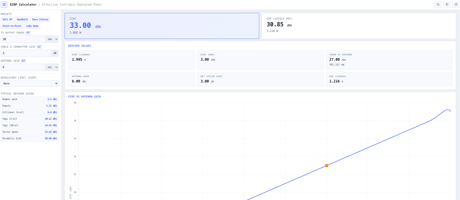
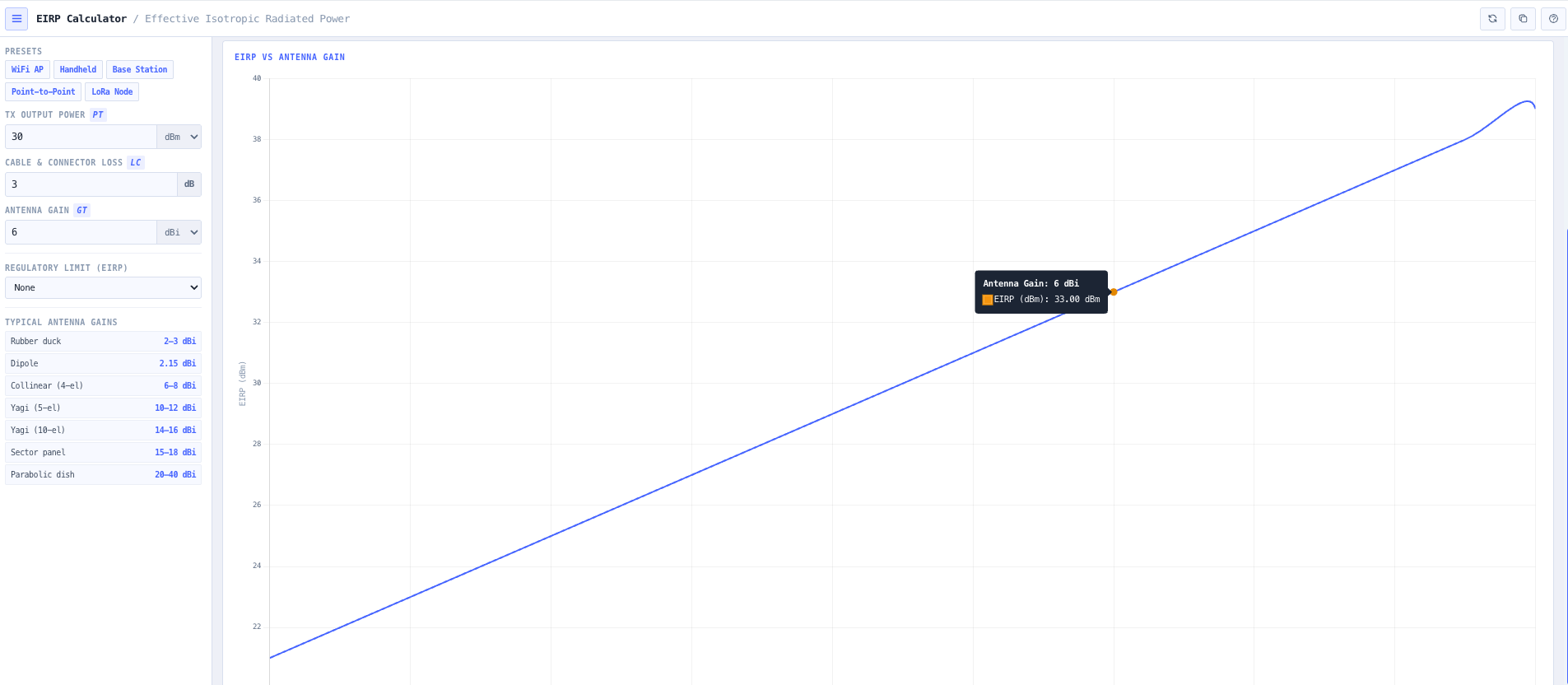
The noIM₃ EIRP Calculator gives a precise, defensible answer in one workspace. The standard relationship EIRP equals Pt minus Lc plus Gt is implemented directly. Inputs are transmitter output power Pt in dBm, total system loss Lc in dB (cable, connector, jumper, combiner, filter), and antenna gain Gt in dBi. Output is EIRP in dBm, watts, milliwatts, and dBW simultaneously, plus the ERP equivalent (referenced to a half wave dipole, lower than EIRP by 2.15 dB) for licence frameworks that specify ERP rather than EIRP.

A full system gain breakdown shows the power at each stage. Transmitter output, power at the antenna input after feeder loss, antenna gain contribution, total system gain, and final EIRP. The breakdown supports troubleshooting (where exactly is the loss happening), optimisation (where is the highest leverage change), and documentation (which stage do you cite in the licence application). Built in presets cover WiFi access points, UHF and VHF handheld radios, cellular base stations, microwave point to point links, and LoRa node configurations so common scenarios are one click away.

Capabilities

EIRP and ERP calculation

Calculates Effective Isotropic Radiated Power using EIRP equals Pt minus Lc plus Gt with consistent dB arithmetic. Effective Radiated Power is also returned, referenced to a half wave dipole. ERP is lower than EIRP by 2.15 dB and is the form some regulatory frameworks specify, so both are surfaced together to remove conversion as a source of compliance error.

Full system gain breakdown

Power at each stage of the transmission chain is reported. Transmitter output, power at the antenna input after feeder loss, antenna gain contribution, total system gain, and final EIRP. The clear separation of stages supports troubleshooting underperforming systems, optimising the highest leverage change, and documenting transmitter compliance for licence applications.

Multi unit power outputs

EIRP and ERP are automatically converted across dBm, watts, milliwatts, and dBW. Useful when an ACMA licence specifies the limit in watts, an internal engineering document expects dBm, and a customer report needs the equivalent in dBW. No mental conversion required between unit families.

Cable, connector, and feeder loss handling

Total system loss Lc accepts the aggregated loss from cable runs, connector and jumper losses, combiner and duplexer insertion loss, and any filter or surge protection in the path. Output explicitly shows the power at the antenna input after losses are applied, so the impact of feeder length and component selection is visible rather than implied.

Preset deployment profiles

Quick select presets for WiFi 2.4 GHz and 5 GHz access points, UHF and VHF handheld radios, cellular base stations, microwave point to point links, and LoRa node configurations. Each preset populates transmitter power, typical feeder loss, and antenna gain so common feasibility questions are one click away. Manual entry remains available for unusual configurations.

EIRP versus antenna gain visualisation

Interactive scaling shows how EIRP increases with antenna gain and how feeder loss reduces radiated power. Useful for evaluating antenna upgrades, longer cable runs, or transmit power changes against an EIRP limit, and for explaining the trade off to non specialist stakeholders.

Compliance support

Output is structured for direct inclusion in ACMA licence applications, internal compliance documentation, and customer engineering reports. Both EIRP and ERP forms are returned alongside the system gain breakdown, so the documented chain from transmitter to radiated power is traceable end to end.

Browser only computation

Runs entirely in your browser. No transmitter power, antenna gain, or licence content is submitted to a server. Useful for commercially confidential cellular and broadcast infrastructure work, defence and security installations, or environments where information security policy prohibits sending engineering data to third party services.

Standards & methodology

  • IEEE 145. Standard definitions of terms for antennas
  • ITU R V.573. Radiocommunication vocabulary
  • ITU radio regulations on EIRP and ERP definition
  • ACMA radiocommunications licence conditions referencing EIRP and ERP limits
  • FCC Part 15 and Part 90 EIRP limits for unlicensed and licensed services

When to use this tool

  • Validating ACMA radiocommunications licence EIRP limits during commissioning
  • Preparing the radiated power section of an RF link budget
  • Optimising antenna selection for wireless and microwave systems against an EIRP cap
  • Assessing feeder length and cable type impact on radiated power
  • Documenting transmitter compliance for licence applications and renewals
  • Evaluating the effect of antenna upgrades or transmit power changes
  • Producing engineering evidence for FCC Part 15 and Part 90 EIRP compliance
  • Sanity checking vendor proposed system designs against EIRP limits
  • Auditing an inherited installation against current licence EIRP conditions
  • Comparing two candidate transmitter and antenna combinations for the same EIRP target
  • Calculating ERP for older licence frameworks that specify ERP rather than EIRP
  • Producing transmitter compliance evidence during ACMA spectrum audits

Is this the right tool for you?

Reach for the EIRP Calculator in any of the following situations.

  • You are commissioning a transmitter system and need to confirm that the actual radiated power matches the EIRP limit on the ACMA radiocommunications licence.
  • You are designing a new wireless or microwave link and need to choose between a higher gain antenna and a lower transmit power to meet an EIRP cap.
  • You are evaluating whether an antenna upgrade will push your radiated power above the licensed EIRP limit before approving the change.
  • You are responsible for an FCC Part 15 unlicensed deployment and need to confirm the system stays within the relevant EIRP limit at the operating frequency.
  • You are responsible for an FCC Part 90 licensed deployment and need to document the transmitter and antenna chain against the EIRP authorised on the licence.
  • You are evaluating the impact of a longer cable run or a higher loss connector chain on radiated power before approving the installation.
  • You are producing the radiated power section of a link budget and need EIRP in the same unit family the rest of the budget uses.
  • You are sanity checking a vendor proposed transmitter and antenna combination against an EIRP requirement before signing off the procurement.
  • You are auditing an inherited installation and want to confirm whether the current configuration meets the EIRP conditions on the active licence.
  • You are calculating ERP for a licence framework or specification that uses ERP rather than EIRP and need a clean conversion alongside the EIRP value.
  • You are responding to an ACMA spectrum audit or compliance enquiry and need defensible engineering output documenting the transmitter to antenna chain.
  • You are training new RF engineers in the EIRP calculation and want a teaching tool that exposes the system gain breakdown stage by stage.
  • You are evaluating two candidate transmitter and antenna combinations that both meet the same EIRP target but differ in cost or coverage shape.
  • You are responsible for a tower top installation and need to verify that feeder loss between the radio and the antenna does not push radiated power below the design target.
  • You are operating under a security regime that prohibits sending engineering data to third party services and need an EIRP calculator that runs entirely in your browser.

Frequently asked questions

What formula does the calculator use?

EIRP equals Pt minus Lc plus Gt, all in dB. Pt is transmitter output power in dBm. Lc is total system loss in dB (cable, connectors, jumpers, combiners, filters). Gt is antenna gain in dBi. The result is EIRP in dBm, with simultaneous output in watts, milliwatts, and dBW. ERP is also returned, referenced to a half wave dipole rather than an isotropic radiator, and is 2.15 dB lower than EIRP for the same configuration.

What is the difference between EIRP and ERP?

EIRP (Effective Isotropic Radiated Power) is the radiated power referenced to an ideal isotropic radiator. ERP (Effective Radiated Power) is the same physical quantity but referenced to a half wave dipole. Because a half wave dipole has 2.15 dB of gain over isotropic, ERP is 2.15 dB lower than EIRP for the same actual radiated power. Australian ACMA conditions and ITU radio regulations typically use EIRP. Some older broadcasting and amateur frameworks still use ERP. Both are surfaced together so the conversion is never a source of compliance error.

What losses should I include in Lc?

Total system loss between the transmitter output and the antenna input. This typically includes coaxial cable loss (in dB per metre at the operating frequency, multiplied by length), connector loss (typically 0.1 to 0.5 dB per connector pair), jumper losses, combiner or duplexer insertion loss, filter insertion loss, and any surge protection or lightning arrester loss. Output explicitly shows the power at the antenna input so the impact of each component is visible.

Does the calculator handle gain in dBd?

Antenna gain is expected in dBi (referenced to an isotropic radiator), which is the IEEE 145 standard definition. If your antenna datasheet quotes gain in dBd (referenced to a half wave dipole), add 2.15 dB to convert to dBi before entering. Many vendor datasheets quote dBd without saying so, and the 2.15 dB difference is the most common source of EIRP calculation errors.

How does this support ACMA compliance?

ACMA radiocommunications licence conditions typically specify a maximum EIRP at the antenna for the licensed frequency. The calculator returns EIRP in the unit family the licence uses (most commonly watts), shows the system gain breakdown so the licence application can document the transmitter, feeder, and antenna chain explicitly, and supports the configuration of a regulatory limit so compliance margin in dB is reported alongside the result.

How is this different from the Antenna Power Density Calculator?

The EIRP Calculator computes the radiated power against transmitter compliance limits expressed as EIRP. The Antenna Power Density Calculator extends that to human exposure assessment, returning power density, electric field, magnetic field, and minimum safe distance against ARPANSA, ICNIRP, and FCC reference levels. Use EIRP for transmit power compliance against a licence EIRP cap. Use power density for human exposure compliance against ARPANSA and equivalent international references.

Does any data leave my browser?

No. The calculator runs entirely in your browser. No transmitter power, antenna gain, or licence content is submitted to a server. Useful for commercially confidential cellular and broadcast infrastructure work, defence and security installations, or environments where information security policy prohibits sending engineering data to third party services.

Can I use this for unlicensed bands?

Yes. EIRP limits are central to unlicensed band frameworks (FCC Part 15, ACMA class licences for ISM bands, RED for European deployments). The calculator handles WiFi 2.4 GHz, WiFi 5 GHz, LoRa 915 MHz, and other ISM bands directly, and the configurable regulatory limit feature lets you check compliance margin against the relevant cap at the operating frequency.