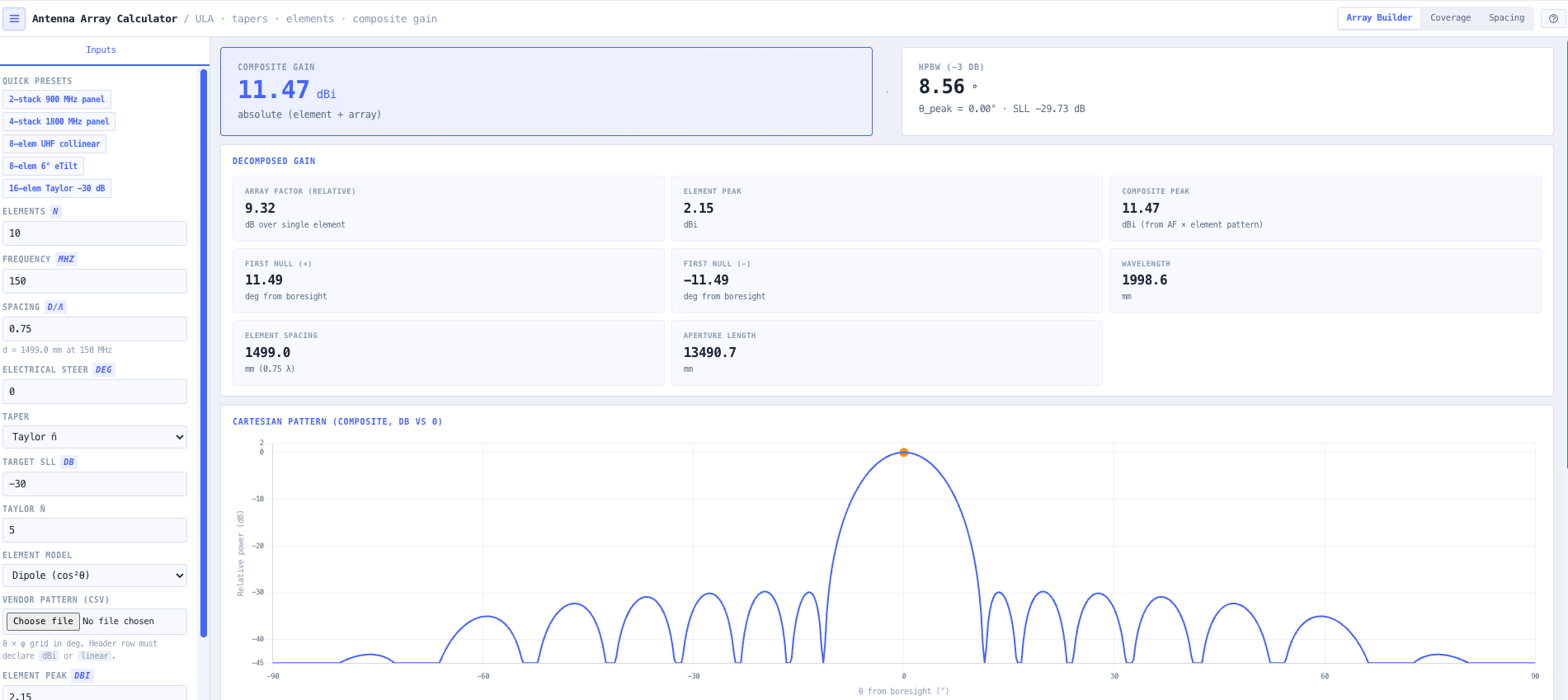
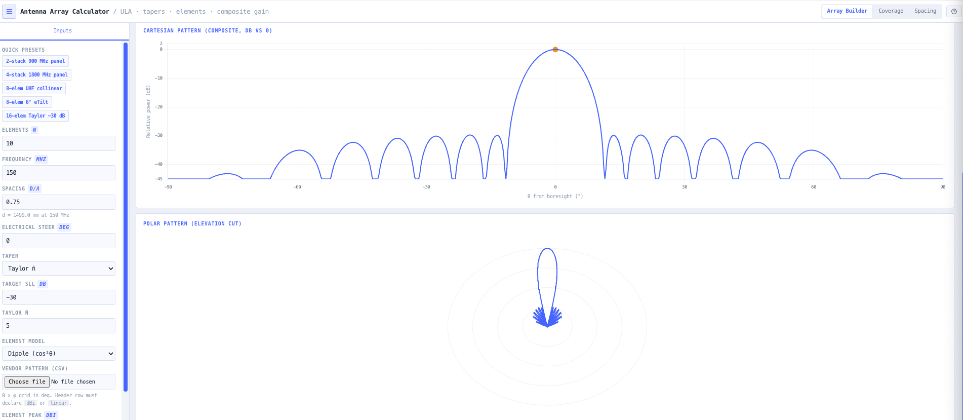
Uniform linear array (ULA) factor with electrical beam steering for stacked panels, collinear columns, downtilted sectors, and beam steered planar arrays. Live polar and cartesian patterns plus extraction of peak gain, half power beamwidth, sidelobe level, and first null positions.
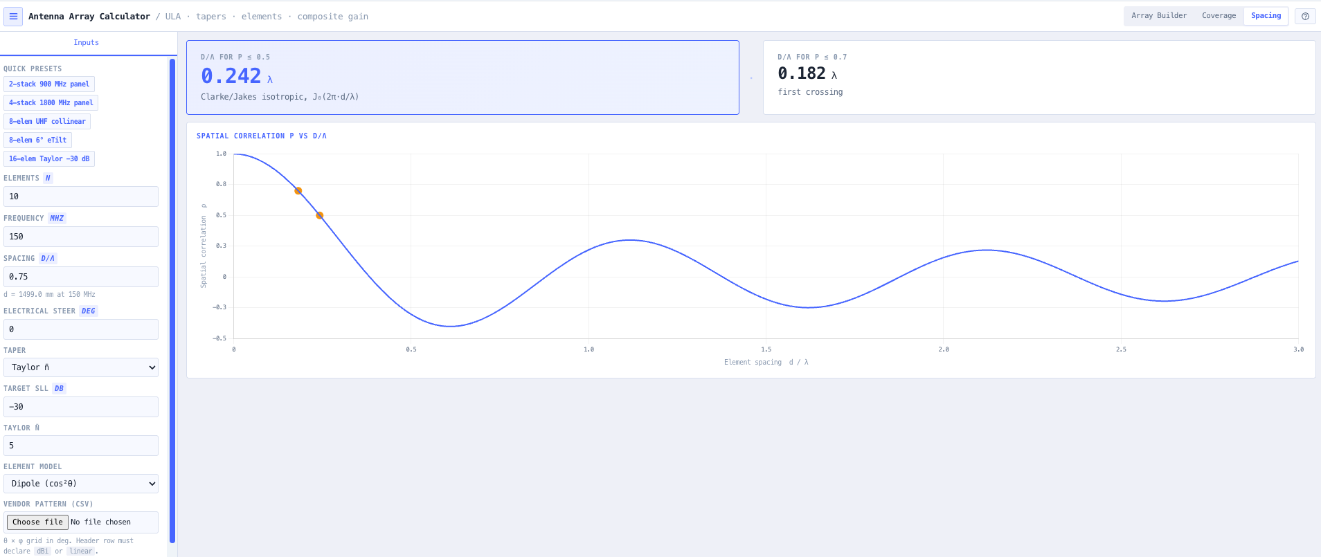
Top bar with the Array, Coverage, and Spacing mode selector.
Overview
What the Antenna Array Calculator does
Stacked panel arrays, collinear columns, downtilted sectors, and beam steered planar arrays all share the same underlying mathematics. The array factor describes how N identical radiating elements combine constructively at the steered direction and partially cancel at off boresight angles. The product of the array factor and the single element pattern gives the total antenna pattern, and for many practical sizing decisions the array factor stage on its own is enough. Engineers want a fast deterministic answer to what does this array do before climbing the tower or before signing off a vendor proposal.
Read the full overview
The noIM₃ Antenna Array Calculator gives that answer. Configure the array the way you would on a real installation. Number of elements N. Inter element spacing as a fraction of wavelength d over lambda. Operating frequency. Electrical steering angle (the progressive phase shift between adjacent elements that steers the main beam). Polar and cartesian pattern plots update live as the configuration changes. Result cards report peak gain (10 log of N for uniform unit weights), half power beamwidth, sidelobe level, and first null directions, which are the numbers that go on a coverage proposal or sector design document.
A validated truth kernel underpins the calculation. The array factor engine is locked by a regression test suite asserting magnitude of array factor squared at the peak direction equals N squared to floating point tolerance, null positions match arcsin (k lambda divided by N d) within 0.02 degrees, sidelobe levels match closed form values, and electrical steering preserves coherent peak power. The aim is a tool you can trust during a Friday afternoon coverage review. The calculator goes beyond the array factor on its own: amplitude tapers (uniform, binomial, Dolph Chebyshev, Taylor n bar), parametric element models (omni, dipole, cos n, asymmetric sector), and vendor CSV pattern import compose with the array factor to give a full composite radiation pattern. A geometric coverage projection produces flat earth main beam range and inner and outer half power edges for a sized mast and tilt. Pair with the Link Planner for terrain aware coverage.
Capabilities 12
Uniform linear array factor
Closed form complex coherent summation across N identical elements with adjustable inter element spacing d over lambda and progressive electrical phase. Output is the array factor pattern across all observation angles, with peak gain equal to 10 log N for uniform unit weights. Suitable for stacked panel sectors, collinear column antennas, and the array factor component of more complex aperture designs.
Electrical beam steering
Progressive phase delta phi between adjacent elements steers the main beam off broadside. Configure the steering angle directly and the array factor pattern updates live. Useful for downtilted cellular sectors, electrically steered phased arrays, and any application where mechanical tilt is replaced by electrical phase shift in the feed network.
Polar and cartesian pattern plots
Live polar pattern view shows the radiation pattern in azimuth or elevation depending on the array geometry. Cartesian pattern view shows the same data on a linear angle axis with dB scale, which exposes the sidelobe structure and the first null positions clearly. Both plots update live as element count, spacing, and steering change.
Result extraction
Peak gain in dB equals 10 log N for uniform unit weights. Half power beamwidth (HPBW) extracted automatically from the pattern. Sidelobe level (SLL) measured against the closed form references. First null positions extracted from the arcsin (k lambda divided by N d) formula and refined by pattern interpolation. The four numbers go directly on a coverage proposal or sector design.
Validated truth kernel
Regression test suite locks the array factor engine to textbook references. Magnitude of array factor squared at the peak direction equals N squared to floating point tolerance. Null positions match arcsin (k lambda divided by N d) within 0.02 degrees. Sidelobe levels match closed form values. Electrical steering preserves coherent peak power. The result is a tool engineers can trust on a Friday afternoon coverage review without second guessing the maths.
Phase convention transparency
Phase convention surfaced explicitly. Positive progressive phase delta phi steers the main beam to positive theta. Broadside is 0 degrees. The convention matches standard antenna textbooks and is documented in the calculator output, removing ambiguity that costs engineers time when they cross check against published patterns.
Site presets
Built in presets for common cellular site frequencies (UHF land mobile, 1800 MHz, 2600 MHz LTE) populate operating frequency for the typical configuration. Combined with a sensible default element count and spacing, a usable answer is one click away for the most common sector design questions.
Amplitude tapers
Uniform, binomial (sidelobe free at half wavelength spacing), Dolph Chebyshev (prescribed sidelobe level), and Taylor n bar (controlled near in sidelobe envelope) tapers. Aperture efficiency loss is applied automatically so the composite peak gain reflects the chosen taper rather than the naive 10 log N figure.
Element pattern composition
Parametric element models (omni, half wave dipole, cos n with fitted half power beamwidth, asymmetric sector with separate elevation and azimuth beamwidths and a front to back floor) compose with the array factor in linear power so coherent interference is preserved. Vendor pattern CSV upload (theta by phi grid, dBi or linear units) drops a real datasheet pattern straight into the composition.
Grating lobe detection
When inter element spacing and steering angle conspire to push a grating lobe into the visible region the tool flags it explicitly, marks the predicted angles on the cartesian pattern plot, and suggests the maximum spacing that would suppress it. Catches the failure mode that quietly destroys a phased array beam pattern when an engineer pushes spacing past half wavelength without checking the steering range.
Geometric coverage projection
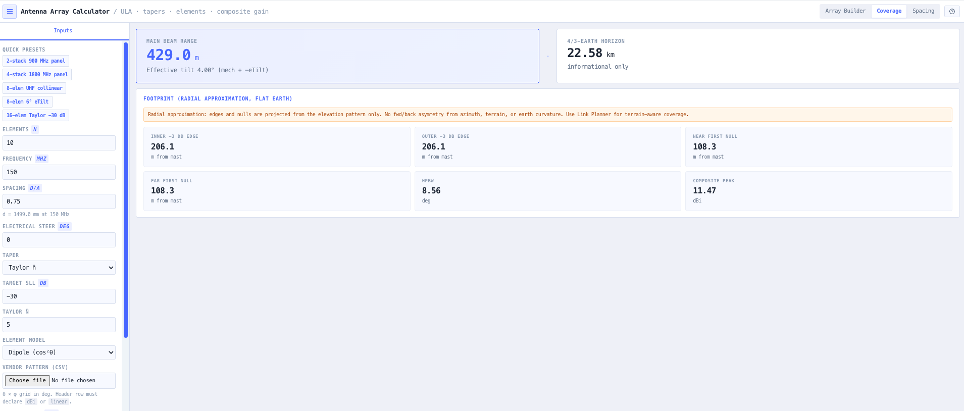
Flat earth main beam range, inner and outer half power edges, and near and far first null distances for a sized mast height and downtilt. Effective downtilt combines mechanical tilt and negative electrical steer in a single source of truth so the array view and coverage view cannot disagree. Geometry sanity warnings fire when the combined tilt points the main beam above the horizon or directly into the ground.
Browser only computation
Runs entirely in your browser. No array configuration, frequency, or design data is submitted to a server. Useful for commercially confidential antenna design, defence and intelligence array work, and environments where information security policy prohibits sending engineering data to third party services.
Inputs and outputs
What goes in, what comes out
Inputs 5
Number of array elements N
Inter element spacing as a fraction of wavelength d over lambda
Operating frequency in MHz or GHz
Electrical steering angle in degrees (progressive phase delta phi between adjacent elements)
Optional site preset (UHF land mobile, 1800 MHz, 2600 MHz)
Outputs 8
Array factor pattern (polar and cartesian)
Peak gain in dB equals 10 log N for uniform unit weights
Peak direction in degrees (steering angle)
Half power beamwidth (HPBW) in degrees
Sidelobe level (SLL) in dB
First null positions in degrees on both sides of the main beam
Phase convention documentation
Validation status against textbook reference cases
Standards & methodology
IEEE 145. Standard definitions of terms for antennas
Balanis Antenna Theory analysis and design textbook formulations for uniform linear array factor
Stutzman and Thiele Antenna Theory and Design textbook formulations
Closed form null position arcsin (k lambda divided by N d) for uniform linear arrays
Standard 13.3 dB sidelobe level for uniform amplitude eight element broadside ULA
Use cases
When to use this tool
01Sizing stacked panel arrays for cellular sector coverage
02Estimating electrical downtilt requirements before a site visit
03Verifying expected beamwidth for collinear column antennas
04Sanity checking vendor antenna datasheet patterns against the underlying array factor
05Teaching array factor theory with live polar and cartesian pattern plots
06Designing electrically steered phased arrays for radar, satellite, and 5G applications
07Comparing element count tradeoffs for a target beamwidth and gain
08Comparing inter element spacing options against grating lobe risk
09Producing array pattern evidence for engineering reports and design reviews
10Validating that a candidate sector configuration meets coverage and sidelobe requirements
11Supporting cellular site optimisation through electrical tilt and steering analysis
12Quick array factor cross check against full electromagnetic simulation output
For an array of N identical radiating elements, the array factor describes how the elements combine coherently at the steered direction and partially cancel at off boresight angles. It is independent of the element pattern. The total antenna pattern is the product of the array factor and the single element pattern. For many practical sizing decisions (sector coverage beamwidth, downtilt geometry, sidelobe level), the array factor stage on its own is enough. The calculator computes the array factor of a uniform linear array with adjustable element count, spacing, and steering.
What does electrical steering do?
Applying a progressive phase shift delta phi between adjacent elements steers the main beam off broadside. The steering angle theta s satisfies sin theta s equals (delta phi divided by 2 pi) times (lambda divided by d), where d is inter element spacing and lambda is wavelength. Used for cellular sector downtilt (replacing mechanical tilt with electrical phase), phased array radar, satellite tracking arrays, and 5G NR FR2 beam steering. The calculator handles steering directly with the steering angle as a configurable input.
What spacing should I use?
Half wavelength spacing (d equals lambda over 2) is the standard for most arrays because it avoids grating lobes (additional main beams that would appear at larger spacing). Smaller spacing reduces grating lobe risk further but reduces aperture and gain. Larger spacing (d greater than lambda over 2) increases gain but at risk of grating lobes when the beam is steered off broadside. The calculator surfaces the array factor across the angle range so grating lobes are visible directly when they appear.
How is HPBW extracted?
Half power beamwidth is extracted directly from the computed array factor pattern by finding the angles where the pattern drops by 3 dB from the peak on either side of the main beam. The result is in degrees and is reported alongside the peak gain and sidelobe level. For uniform unit weight ULA at half wavelength spacing, HPBW is approximately 51 divided by N times cos of the steering angle, in degrees, which the calculator confirms numerically.
What is the sidelobe level for a uniform array?
A uniform amplitude weighted ULA has sidelobe level approximately minus 13.3 dB relative to the main beam, regardless of N (above approximately 8 elements). Lower sidelobes require non uniform amplitude weighting. The calculator implements uniform, binomial, Dolph Chebyshev (prescribed sidelobe level) and Taylor n bar tapers directly. The composite peak gain accounts for the aperture efficiency loss the taper introduces so the reported figure matches what the array will actually deliver.
How is null position calculated?
For a uniform linear array, null positions follow arcsin (k lambda divided by (N d)) for k equals 1, 2, 3, etc, measured from the steered direction. The calculator uses this closed form for the first null and refines the result by pattern interpolation if needed. Null positions are useful for null steering applications where an interferer can be placed deliberately at a null direction to suppress it.
How does this support full antenna design and link planning?
The array factor is one component of the full antenna pattern. The total pattern is the product of the array factor and the single element pattern. For full antenna design including element pattern modelling, use the noIM₃ Antenna Builder. For coverage planning across terrain with the resulting antenna pattern, use the noIM₃ Link Planner. Use the Antenna Array Calculator for array factor intuition and beam steering geometry decisions.
Does any data leave my browser?
No. The calculator runs entirely in your browser. No array configuration, frequency, or design data is submitted to a server. Useful for commercially confidential antenna design, defence and intelligence array work, and environments where information security policy prohibits sending engineering data to third party services.