Five-mode thermal and airflow workstation for comms cabinets: roll up the rack heat load, size the ventilation airflow and cooling capacity, check the inlet against the ASHRAE envelopes, and assess sealed outdoor enclosures (passive vs forced vs active). Imports the equipment list from the Rack Layout Designer.
Free on a Standard account, with no time limit. No credit card.
Rack Heat Load Designer
8 inputs→8 outputs
Walkthrough
See it working
Rack Heat Load Designer
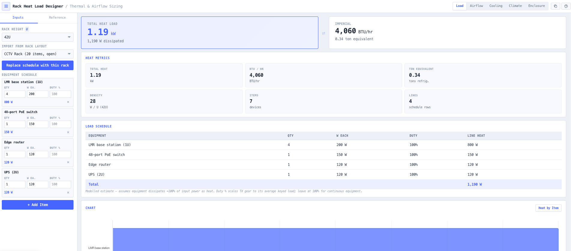
Load mode: equipment schedule rolling up to total heat load, with a per-line duty cycle.
Overview
What the Rack Heat Load Designer does
A communication or equipment cabinet does not stop at the layout. Once the switches, routers, base stations, amplifiers, and UPS are placed, the next question is thermal: how much heat does this cabinet dissipate, how much air do I have to move through it to hold a sensible inlet-to-outlet temperature rise, how much installed cooling do I have to commission, and will the cold-aisle inlet sit inside the ASHRAE envelope the gear is rated to. Get the roll-up wrong and the HVAC contractor is handed a load figure that under-sizes the plant; get the airflow wrong and the rack runs hot at altitude where thinner air carries less heat per unit volume; assume a sealed roadside cabinet can shed its heat passively when it cannot and the equipment cooks in the sun.
Read the full overview
The noIM₃ Rack Heat Load Designer is the dedicated thermal calculator the Rack Layout Designer defers to. It follows the dB Conversion Calculator shell pattern: a five-mode top bar — Load, Airflow, Cooling, Climate, and Enclosure — a slide panel with an Inputs tab and a Reference tab, a result canvas with a headline conversion pair and a derived-metrics grid, a per-mode reference table, a per-mode chart, and a Copy results button. The equipment list can be imported directly from a saved or currently-open Rack Layout Designer cabinet, so the cabinet contents are not re-keyed; the placed items are aggregated by equipment type into named rows of quantity and per-device draw and remain fully editable.
This is an honest modelled estimate, not a CFD study. Every figure is derived from a standard textbook constant — 1 W = 3.412 BTU/hr, 1 ton = 3.517 kW = 12 000 BTU/hr, the 1.08 sensible-heat constant, the 1206 J/m³K volumetric heat capacity of air, and the ISA density model — anchored to the equipment draw you enter. The typical per-device heat figures in the Reference tab are labelled as typical class values that must be verified against the nameplate. The tool models sensible heat only and explicitly does not perform CFD, hot-aisle recirculation, latent-load, or floor-loading analysis. All computation is client-side, the schedule and parameters persist in localStorage, and the active mode result copies to the clipboard in a spreadsheet-friendly format.
Capabilities 9
Load: equipment heat roll-up
Build the cabinet equipment schedule as named rows of quantity, typical per-device draw, and a transmit/utilisation duty cycle. The tool rolls the heat up to the total in watts, kilowatts, and BTU/hr, the ton-of-refrigeration equivalent, and the average W/U density over the selected rack height (12U, 24U, 42U, or 47U). The roll-up assumes equipment dissipates approximately 100 percent of its input power as heat, with the per-line duty cycle scaling TX equipment that is not keyed continuously to its average keyed load (left at 100 percent for continuous gear). A labelled typical-equipment-heat reference table (switch, router, server, base station, amplifier, UPS, PDU, patch panel) is provided for sanity-checking; passive items such as patch panels and fibre trays dissipate effectively no heat.
Airflow: ventilation sizing with altitude derate
Airflow mode sizes the ventilation volume needed to hold a chosen inlet-to-outlet temperature rise for the rack heat load, using the sensible-heat equation (Q in m³/h = P × 3600 / (1206 × ΔT in °C), and CFM = BTU/hr / (1.08 × ΔT in °F)). Results are reported in m³/h, CFM, and L/s, with an airflow-versus-ΔT table for quick what-if comparison. A site-altitude input applies an ISA air-density derate: thinner air at altitude carries less heat per unit volume, so the required volume scales up, and both the sea-level and altitude-corrected figures are shown along with the percentage uplift.
Cooling: refrigeration capacity sizing
Cooling mode sizes the installed cooling capacity from the heat load, a design margin, and a redundancy scheme. Installed capacity is heat load × (1 + design margin) × redundancy factor, where N+1 and N+2 scale the installed plant by (n+1)/n and (n+2)/n over the number of units sharing the duty. Results are reported in kW, tons of refrigeration, and BTU/hr, with the per-unit duty and a side-by-side N, N+1, N+2 comparison table. This is sensible-capacity sizing; latent load and unit derating must be confirmed against the CRAC or split-system datasheet.
Climate: ASHRAE TC9.9 envelope check
Climate mode checks the cold-aisle inlet temperature against the ASHRAE TC9.9 thermal guidelines. The recommended band of 18-27 °C applies to all classes; each class adds a wider allowable dry-bulb envelope (A1 15-32 °C, A2 10-35 °C, A3 5-40 °C, A4 5-45 °C). The tool classifies the inlet as Recommended, Allowable, or Exceeds, colours the headline card accordingly, and reports the headroom in degrees to both the recommended maximum and the selected class allowable maximum.
Enclosure: sealed outdoor cabinet assessment
Enclosure mode assesses a sealed outdoor cabinet (IP/NEMA) where heat is shed through the enclosure surface rather than by through-flow air. It computes the effective dissipating area from the cabinet dimensions and mounting (free-standing or wall-mounted) per IEC 60890, and the passive dissipation capability Q = k × A × ΔT, where k is the still-air combined convection and radiation coefficient for the surface material (painted steel 5.5, stainless 3.7, aluminium 12, polyester 3.5 W/m²K). Comparing the internal heat load plus any solar gain against the passive capability, the tool returns a verdict on a decision ladder: sealed passive (with the resulting internal temperature), forced ventilation (with the required airflow, only viable when ambient is below the allowable internal temperature), or active cooling (with the required capacity in kW).
Import from the Rack Layout Designer
In Load mode the equipment schedule can be imported directly from a saved or currently-open Rack Layout Designer cabinet. The placed items are aggregated by equipment type into named rows of quantity and per-device draw, so the cabinet contents are not re-keyed. Passive items (zero watts) are kept so the schedule mirrors the rack. After import the schedule is fully editable, including the per-line duty cycle.
Per-mode reference tables and charts
Each mode carries its own reference table and chart: the typical-equipment-heat table in Load, the airflow-versus-ΔT comparison in Airflow, the N / N+1 / N+2 capacity comparison in Cooling, and the ASHRAE recommended and allowable bands in Climate. The result canvas pairs a headline conversion (for example kW alongside BTU/hr) with a derived-metrics grid so the key figure and its supporting numbers are read together.
Honest modelling and clipboard output
Every figure is a modelled estimate derived from a standard textbook constant (1 W = 3.412 BTU/hr, 1 ton = 3.517 kW = 12 000 BTU/hr, the 1.08 sensible-heat constant, the 1206 J/m³K volumetric heat capacity of air, and the ISA density model), anchored to user-entered equipment draw. Typical equipment heat figures are labelled as typical class values to be verified against the nameplate. The active mode result block copies to the clipboard in a spreadsheet-friendly format, and the equipment schedule and parameters persist in localStorage between sessions.
Browser-based, client-side computation
All computation runs entirely in your browser with no backend. The equipment schedule, mode parameters, and results never leave the machine. Useful where equipment lists and site thermal data are commercially confidential, and convenient for working offline on a site walk or in a remote shelter.
Inputs and outputs
What goes in, what comes out
Inputs 8
Rack height (12U, 24U, 42U, or 47U) for the W/U density metric
Equipment schedule rows: name, quantity, typical per-device draw in watts, and transmit/utilisation duty cycle
Target inlet-to-outlet temperature rise (ΔT) for airflow sizing
Site altitude for the ISA air-density derate
Design margin and N, N+1, or N+2 redundancy scheme for cooling
Number of cooling units sharing the duty
Cold-aisle inlet temperature and ASHRAE class (A1-A4) for the envelope check
Sealed-enclosure dimensions, surface material, mounting, design ambient, allowable internal temperature, and solar gain
Outputs 8
Total rack heat load in watts, kilowatts, and BTU/hr
Ton-of-refrigeration equivalent and average W/U density
Required ventilation airflow in m³/h, CFM, and L/s for the target ΔT
Sea-level and altitude-corrected airflow with the percentage uplift
Installed cooling capacity in kW, tons, and BTU/hr with per-unit duty and an N / N+1 / N+2 comparison
Inlet status (Recommended, Allowable, or Exceeds) with headroom to the recommended and class allowable maxima
Sealed-enclosure verdict (passive, forced ventilation, or active cooling) with the resulting internal temperature, required airflow, or required capacity
Active mode result copied to the clipboard in a spreadsheet-friendly format
Standards & methodology
ASHRAE TC9.9 recommended band 18-27 °C (all classes)
ASHRAE TC9.9 allowable dry-bulb envelopes A1 15-32 °C, A2 10-35 °C, A3 5-40 °C, A4 5-45 °C
IEC 60890 effective dissipating area for sealed enclosures
Sensible-heat conversion: 1 W = 3.412 BTU/hr, 1 ton refrigeration = 3.517 kW = 12 000 BTU/hr
ISA air-density model for the altitude derate
Use cases
When to use this tool
01Rolling up the heat load of a communication cabinet from its equipment schedule
02Sizing the ventilation airflow (m³/h or CFM) for a target inlet-to-outlet temperature rise
03Sizing the installed cooling capacity in kW or tons with an N+1 redundancy scheme
04Checking a cold-aisle inlet temperature against the ASHRAE recommended and allowable envelopes
05Deriving the cooling load to hand to the HVAC contractor for a remote equipment shelter
06Comparing the airflow required at sea level versus a high-altitude radio site
07Sanity-checking a cabinet W/U density against the rack height before committing the layout
08Deciding whether a sealed roadside cabinet can shed its heat passively or needs fans or active cooling
09Importing a Rack Layout Designer cabinet to size its ventilation and cooling without re-keying the equipment
How does the tool turn an equipment list into a heat load?
You build a schedule of named rows, each with a quantity, a typical per-device draw in watts, and a transmit/utilisation duty cycle. The tool assumes comms and IT gear dissipate approximately 100 percent of their input power as heat, multiplies quantity by draw by duty cycle per row, and rolls the total up to watts, kilowatts, and BTU/hr, plus the ton-of-refrigeration equivalent and the average W/U density over the selected rack height. The duty cycle is left at 100 percent for continuous gear and lowered for TX equipment that is not keyed continuously.
How is the ventilation airflow sized?
Airflow mode applies the sensible-heat equation. The required volume in m³/h is P × 3600 / (1206 × ΔT in °C), and the CFM form is BTU/hr / (1.08 × ΔT in °F), where ΔT is the inlet-to-outlet temperature rise you choose. Results are reported in m³/h, CFM, and L/s, with an airflow-versus-ΔT table for what-if comparison.
Why does site altitude change the airflow figure?
Air at altitude is thinner and carries less heat per unit volume, so a given heat load needs a larger volumetric airflow to hold the same temperature rise. Entering the site altitude applies an ISA air-density derate; the required volume scales by one over the density ratio, and the tool reports both the sea-level figure and the altitude-corrected figure plus the percentage uplift.
How does the cooling capacity sizing handle redundancy?
Installed capacity is the heat load times one plus the design margin times a redundancy factor. N+1 scales the installed plant by (n+1)/n and N+2 by (n+2)/n over the number of units sharing the duty, so a single unit (or two) can drop out without losing the load. Results are reported in kW, tons, and BTU/hr with the per-unit duty and a side-by-side N, N+1, N+2 comparison. This is sensible-capacity sizing; latent load and unit derating must be confirmed against the CRAC or split-system datasheet.
What does the ASHRAE Climate check tell me?
Climate mode compares the cold-aisle inlet temperature against the ASHRAE TC9.9 thermal guidelines. The recommended band of 18-27 °C applies to all classes, and each class adds a wider allowable dry-bulb envelope (A1 15-32 °C, A2 10-35 °C, A3 5-40 °C, A4 5-45 °C). The inlet is classified as Recommended, Allowable, or Exceeds, and the headroom in degrees to both the recommended maximum and the class allowable maximum is reported.
How does the sealed-enclosure assessment decide passive, forced, or active?
Enclosure mode computes the effective dissipating area from the cabinet dimensions and mounting per IEC 60890 and the passive dissipation capability Q = k × A × ΔT, where k is the still-air convection-plus-radiation coefficient for the surface material (painted steel 5.5, stainless 3.7, aluminium 12, polyester 3.5 W/m²K). It compares the internal heat load plus any solar gain against that capability at the allowable internal-minus-ambient difference and returns a verdict on a decision ladder: sealed passive with the resulting internal temperature, forced ventilation with the required airflow (only viable when ambient is below the allowable internal temperature), or active cooling with the required capacity in kW.
How accurate are the typical equipment heat figures, and does anything leave my browser?
The typical per-device heat figures in the Reference tab are modelled class values labelled as typical and must be verified against the equipment nameplate; every result is a modelled estimate from a standard textbook constant anchored to the draw you enter, not a CFD or measured study, and the tool does not model hot-aisle recirculation, latent load, or floor loading. Computation is entirely client-side: the schedule, parameters, and results never leave your browser, and they persist in localStorage between sessions.