Structures drawn in three dimensions
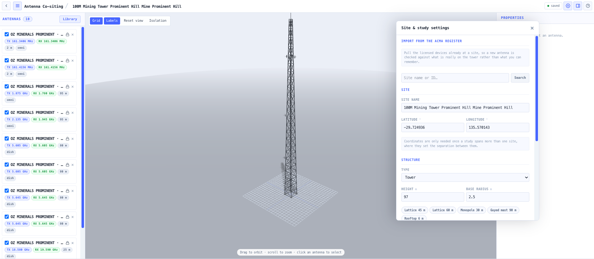
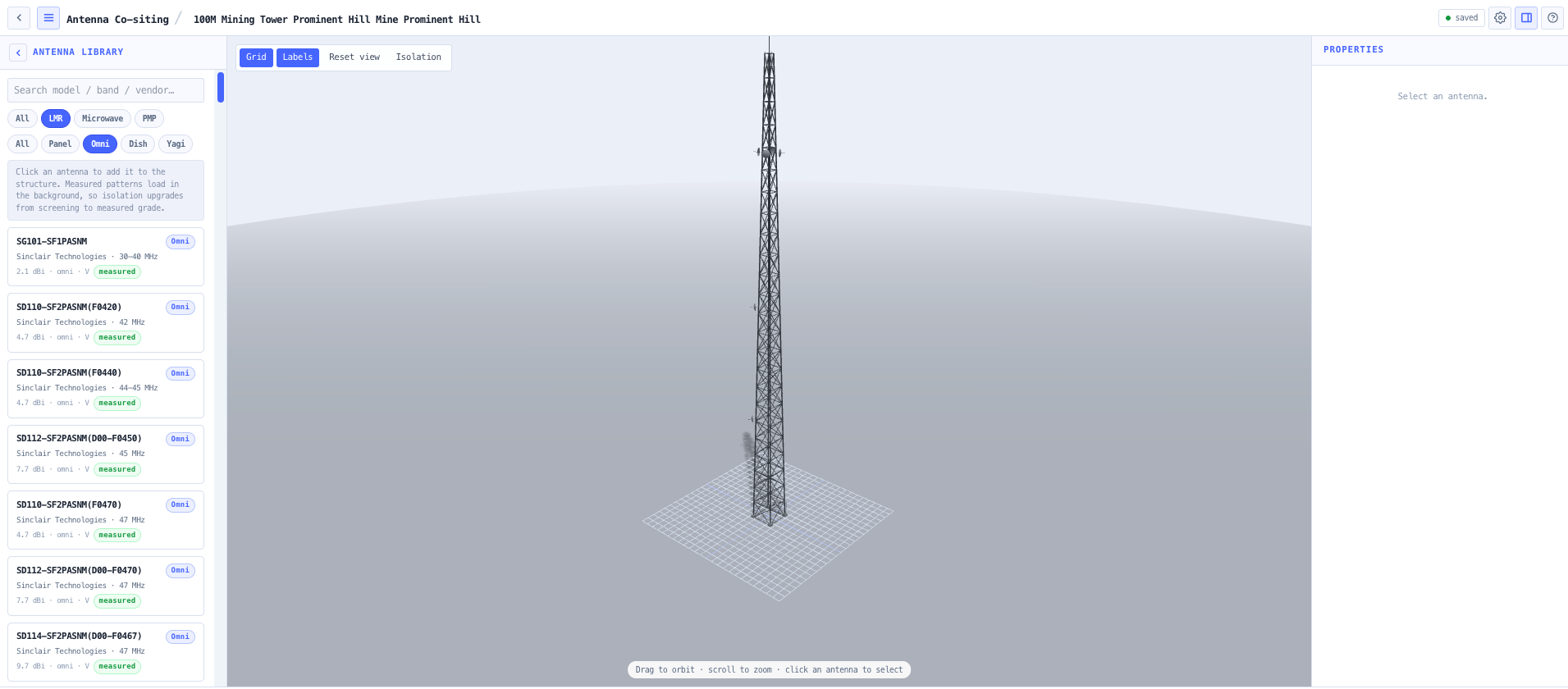
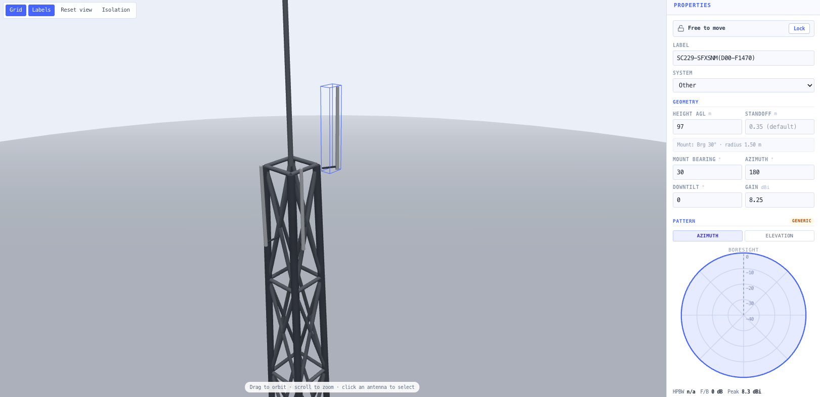
Lattice tower, tower, monopole, guyed mast or rooftop pole, with height and base radius set so the taper follows automatically and mount radius changes with height the way real steel does. Antennas are dragged in the 3D view, snap onto the structure faces and follow the taper, and a standoff places them off the face with the resulting mount radius reported, because horizontal separation is the geometry the isolation models are most sensitive to.
Two isolation models and an honest choice between them
The ITU-R Report M.2244 Annex 4 closed form, codified in SM.337-6, is computed alongside pattern aware Friis using each antenna gain toward the other. Both are always shown with the preferred model and its reason. Where the geometry is a slant rather than purely stacked or side by side, the M.2244 warning that its slant interpolation is not physically derived is carried as a note on the result rather than quietly ignored.
It tells you when it cannot tell you
The vertical closed form holds beyond ten wavelengths of separation, which at 150 MHz is twenty metres, and the horizontal form beyond eight. Below about a fifth of a wavelength the vertical form returns an unphysical negative isolation. Ordinary rooftop spacings sit inside those bounds, so results are graded against the published limits, out of range pairs are counted in the status bar, and an unassessable check is never reported as a pass. A study that reads as clean because nothing could be assessed is the most dangerous output this tool could produce.
Seven land mobile mechanisms, pairwise and whole scene
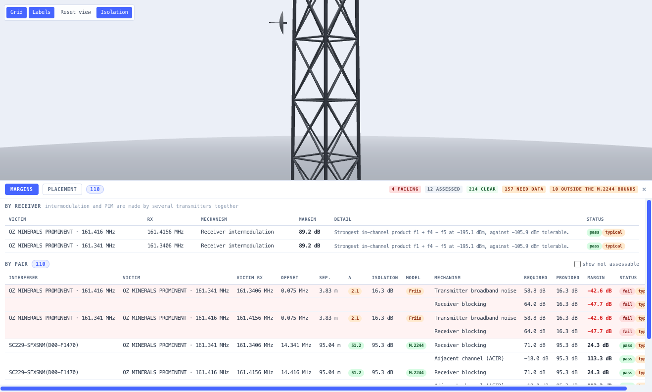
Transmitter broadband noise, receiver blocking, adjacent channel rejection, and harmonics and spurious emission are properties of one transmitter into one receiver and appear per pair. Receiver intermodulation, transmitter intermodulation and passive intermodulation are made by several transmitters together and are reported once per victim receiver. Receiver intermodulation follows ITU-R SM.1134-1 Annex 1 in full, and that Recommendation own worked example is carried as a regression test.
Microwave links assessed as fixed service
Two directional dishes are a fixed service pair and the land mobile susceptibility figures are the wrong model for them, so they are assessed by net filter discrimination instead: the ITU-R F.699 reference pattern for off boresight discrimination and the ETSI EN 302 217 emission and selectivity masks for off tune rejection, judged against an interference to noise criterion under the ACMA RALI FX 3 alternative criteria clause. Dishes in different bands report no interaction rather than a pass on an extrapolated mask.
Receiver figures you can trace to a clause
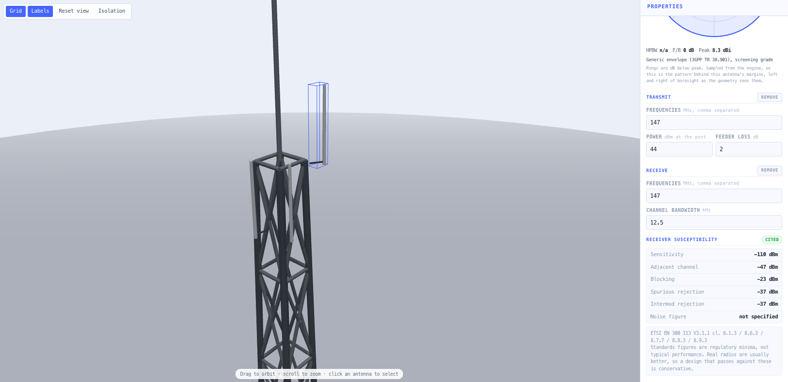
Adjacent channel selectivity, blocking, spurious and intermodulation rejection are seeded from ETSI EN 300 086 for analogue PMR, EN 300 113 for digital PMR, EN 300 392-2 for TETRA, and DMR inheriting EN 300 113 as its own air interface standard directs. Each carries the clause it came from. Noise figure is specified in none of them, so it is asked for rather than assumed, and any field with no cited figure is left empty rather than filled with something plausible.
Measured patterns, with honest grading when there are none
Antennas added from the component catalogue load their real measured radiation patterns in the background, which lifts their coupling figures from screening grade to measured. Antennas built from an archetype use a generic class envelope, which is a screening figure. The status bar states which basis the scene is on and the inspector tags each antenna, so a screening result is never mistaken for a measured one.
Import the site rather than transcribing it
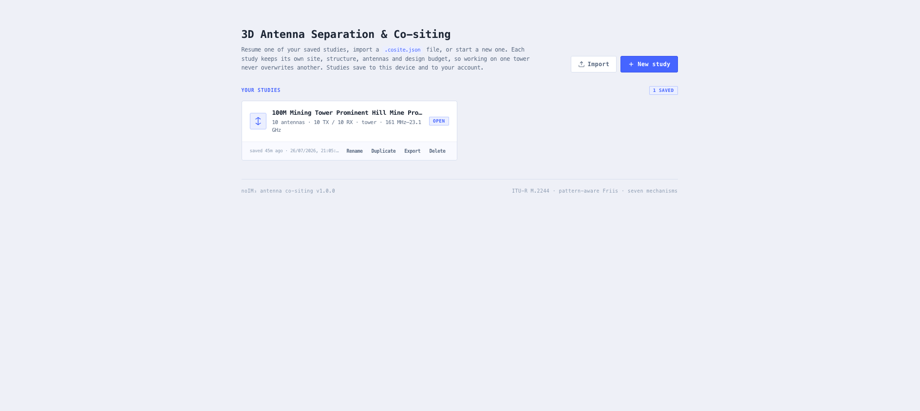
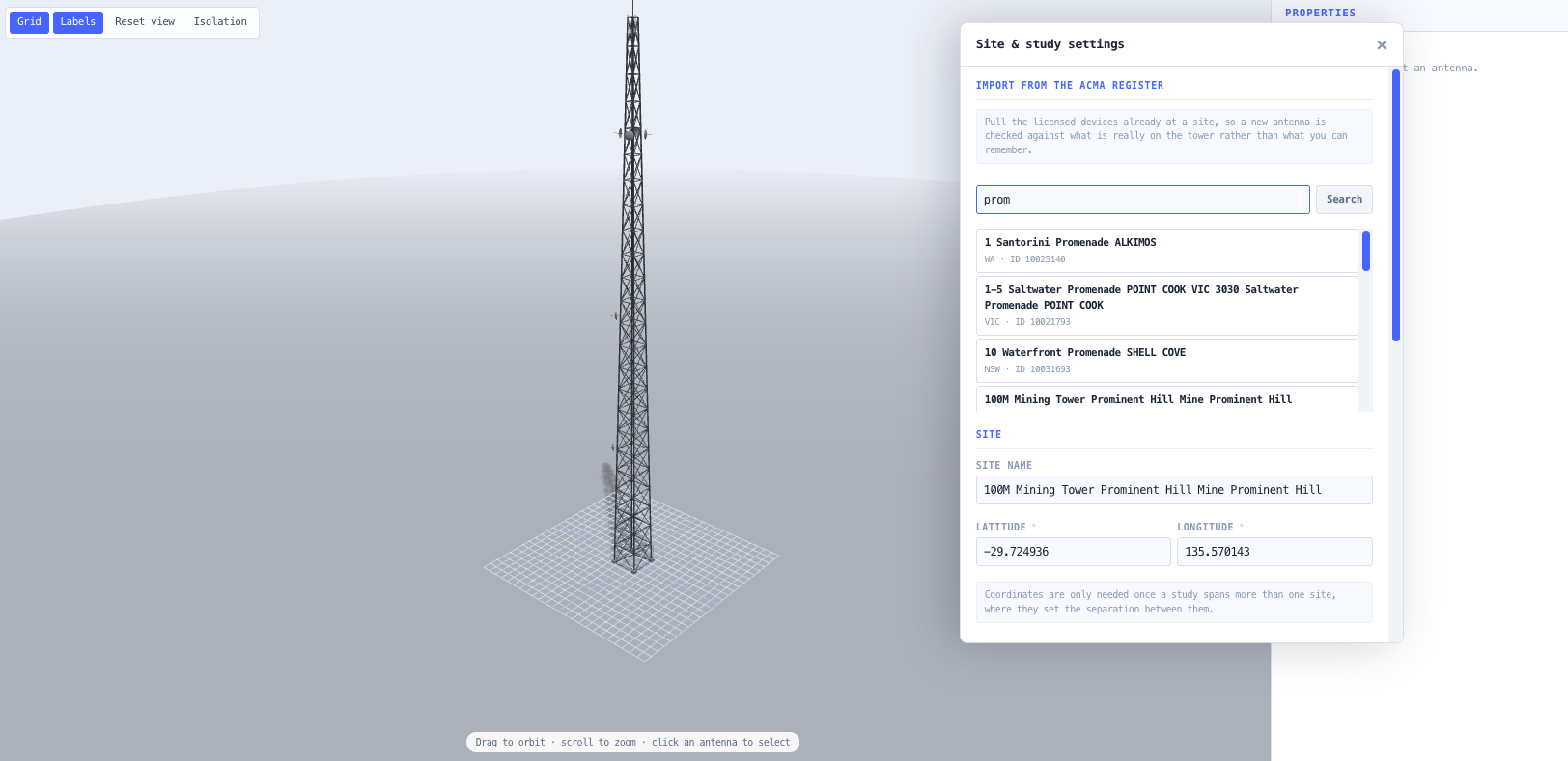
Licensed devices import from the ACMA register by site name or identifier, receive records included, because a co-siting study is transmitters into receivers and an import that kept only transmitters would report a clean study for a tower full of victims. Both importers make their gaps loud: transmit power backed out of EIRP is flagged as assumed, a device with no usable power arrives disabled, and representative receiver figures are tagged as typicals wherever a result rests on them.
Place a new antenna where it clears
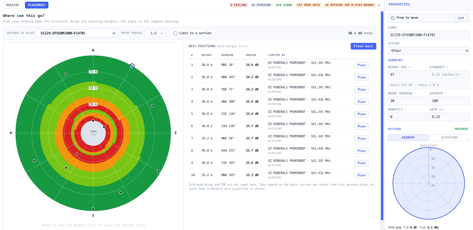
Add an antenna from the library and it drops onto the best position for the frequencies and pattern it carries. From there you place it by clicking the plan view, taking the top ranked spot, or picking from a ranked table of genuinely distinct positions, and the search can be bound to the height band and compass arc the antenna could really occupy. Selecting a licensed antenna draws the same heat map for its fixed position, which answers whether it is already mounted in a poor spot.
Passive intermodulation is measured, not calculated
Passive intermodulation depends on corrosion, contact pressure and dissimilar metals at joints that cannot be seen from a desk. The tool predicts where products land, flags the ones falling in a receiver, and points at inspection and testing. It will not return a level, because any level it returned would be invented. ITU-R SM.1446-0 defines and measures transmitter intermodulation but sets out no prediction formula, and that limit is respected rather than papered over.