Cable Utilities

Cable Loss Calculator

Multi segment coaxial cable loss, VSWR, and power efficiency analysis. Build a cable assembly from RG 58, RG 8, RG 213, LMR 400, Heliax, and other common coax types and see matched loss, mismatch loss, connector loss, signal delay, and total efficiency.

Overview

Coaxial cable loss is the unsung killer of RF system performance. The transmitter is often blamed when sectors underperform, when fade margin disappears in rain events, or when receive sensitivity quietly degrades on a working network. The actual culprit is more often the feeder run. A 30 metre LMR 400 jumper at 5.8 GHz drops over 7 dB by itself. A 30 metre RG 58 at the same frequency drops more than 30 dB and is essentially useless. Connector losses, mismatch loss from a poorly matched antenna, and ageing cable that has absorbed moisture all stack on top. By the time the radiated power reaches the antenna, the budget the design assumed is gone.

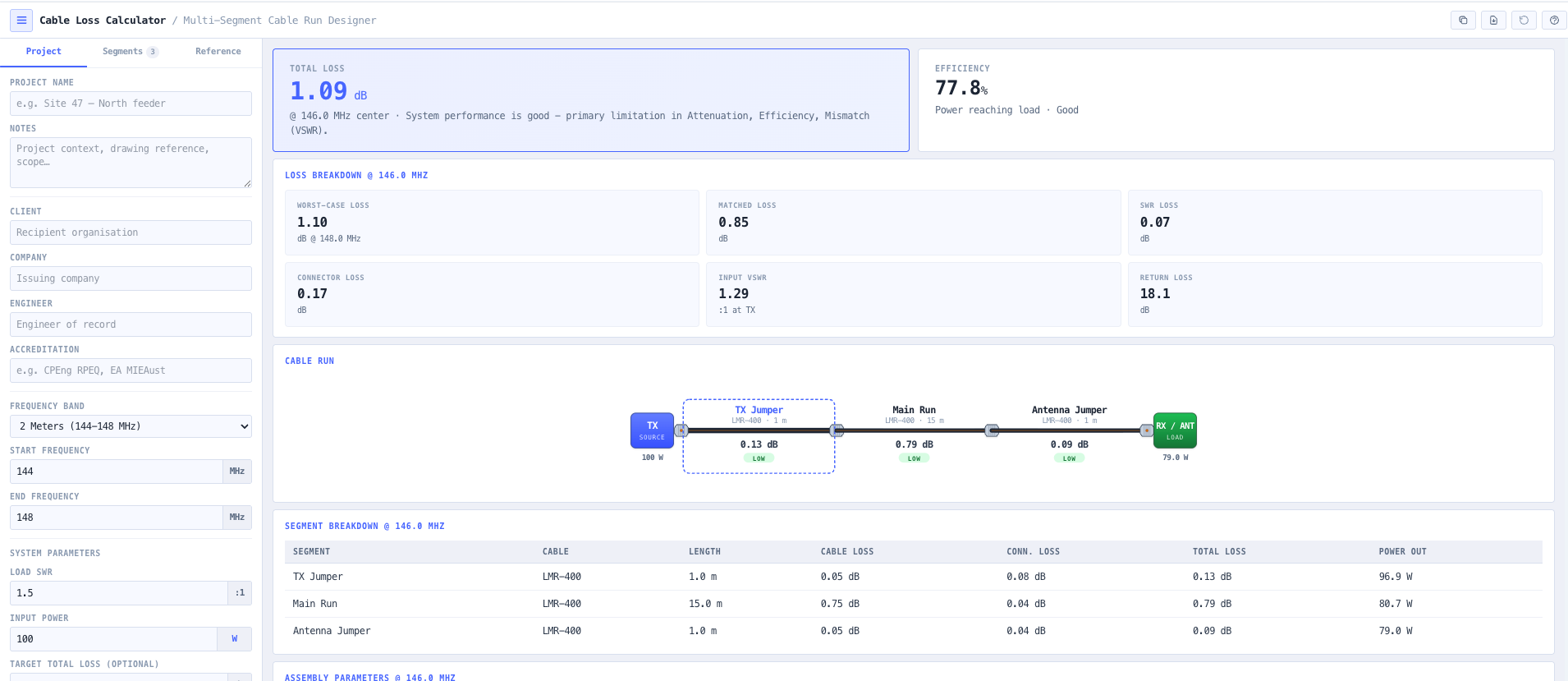
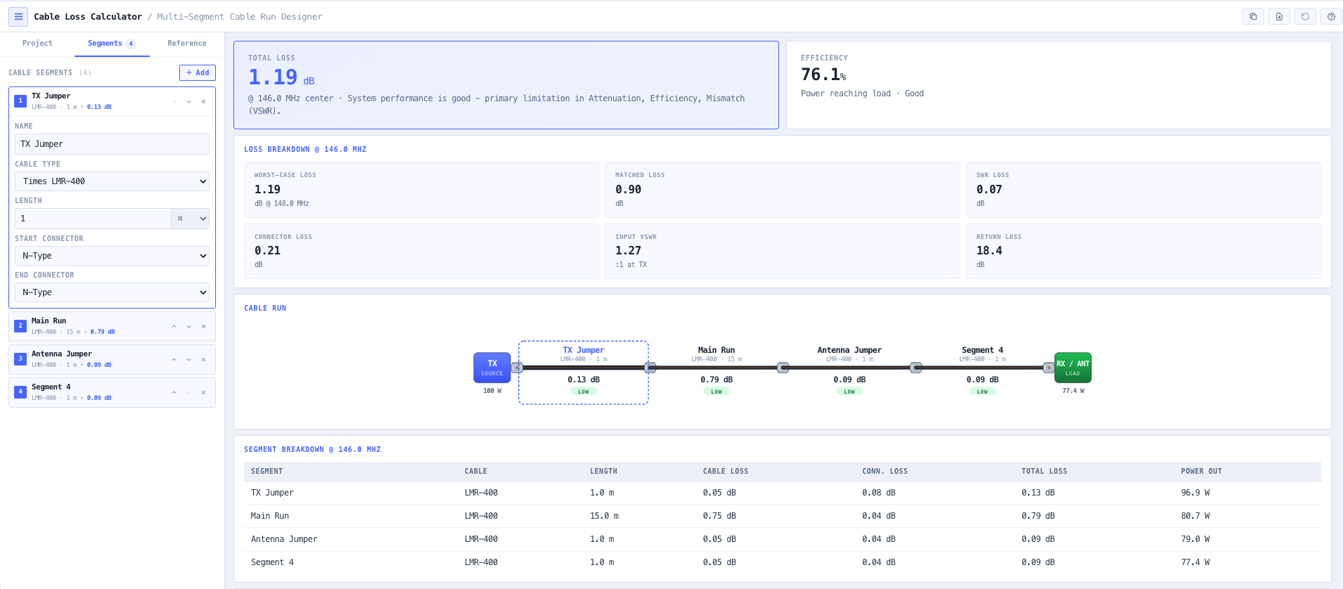
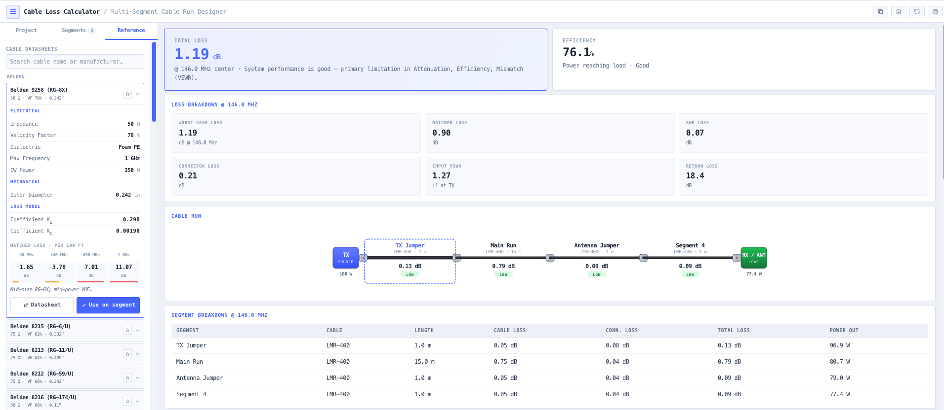
The noIM₃ Cable Loss Calculator gives a precise multi segment analysis of a real world coaxial cable assembly. Build the run from segments with their own cable type, length, frequency, and connectors, and the calculator aggregates matched line attenuation, mismatch loss from load VSWR, connector insertion loss, and total assembly loss. Output covers loss in dB and watts, power in versus power out, total efficiency as a percentage, and a visual loss classification (low, medium, high) for fast assessment. A built in cable database covers the common types (RG 58, RG 8, RG 213, LMR 400, LMR 600, Heliax LDF series, Heliax FSJ series) with frequency dependent attenuation derived from manufacturer coefficients.

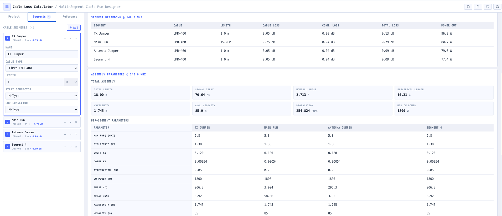
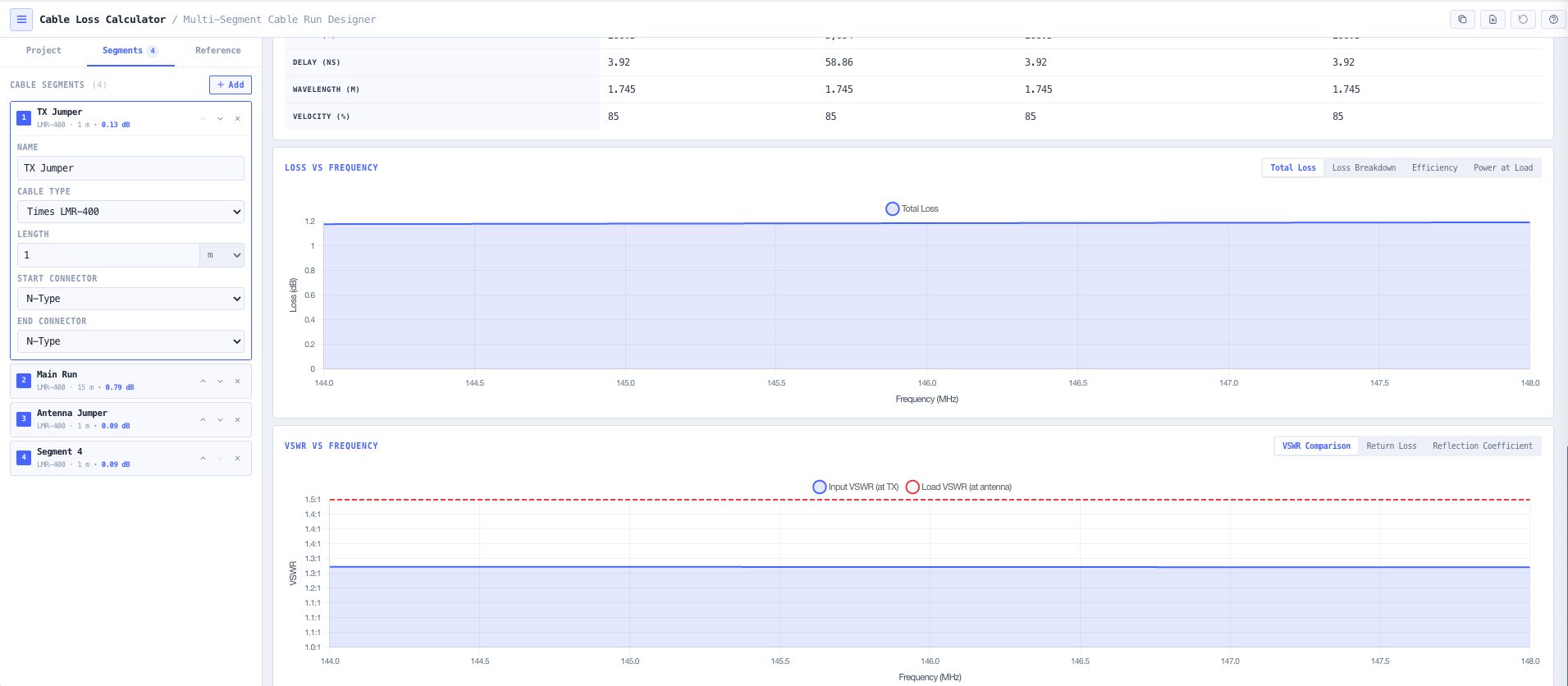
Beyond loss, the calculator returns the propagation and electrical length parameters that matter for phased arrays, timing critical applications, and impedance matching work. Signal delay in nanoseconds. Wavelength at the operating frequency. Velocity factor of the cable. Propagation velocity. Electrical length in wavelengths. Combined with VSWR analysis (return loss, reflection coefficient, input VSWR, mismatch induced additional loss), the workspace covers every transmission line metric an RF engineer would otherwise pull from three different references and a calculator app.

Capabilities

Multi segment cable assembly builder

Construct a real world cable run from multiple segments, each with its own cable type, length, frequency, and connector pair. Suitable for jumper plus feeder plus jumper trunk arrangements typical of cellular and broadcast tower top installations. The calculator aggregates loss across the assembly and reports per segment power output and attenuation.

Matched loss and mismatch (VSWR) loss

Separates matched line attenuation (the loss the cable would have feeding a perfect 50 ohm load) from mismatch induced loss (the additional loss caused by a non matched load). Returns return loss, reflection coefficient, input VSWR, and the additional dB cost of the mismatch so antenna VSWR is not silently absorbed into the cable loss number.

Connector and component loss

Per segment connector insertion loss with sensible defaults for N type, BNC, TNC, SMA, 4.3 to 10, and 7 to 16 DIN connector pairs. Total assembly loss includes the connector contribution explicitly, so the impact of a four connector trunk is visible against the underlying cable loss.

Power flow and efficiency breakdown

Displays power in, power out, total loss in dB and watts, and overall efficiency as a percentage. A visual loss classification (low, medium, high) supports rapid assessment, and the per segment breakdown identifies which segment is consuming the most power so remediation effort is targeted.

Frequency dependent attenuation

Cable attenuation varies with frequency, typically as the sum of a square root term (skin effect) and a linear term (dielectric loss). The calculator uses manufacturer derived K1 and K2 coefficients per cable type, returning realistic loss at the operating frequency rather than a single nominal value taken from one band.

Propagation and electrical length

Returns signal delay in nanoseconds, wavelength at the operating frequency, velocity factor of the cable, propagation velocity, and electrical length in wavelengths. Useful for phased array work where cable length differences translate to phase differences, timing critical applications, and impedance matching where electrical length sets the transformation behaviour.

Cable specification database

Built in database of common coaxial cables. RG 58, RG 8, RG 213, LMR 240, LMR 400, LMR 600, Heliax LDF series, Heliax FSJ series, and others. Each entry exposes dielectric constant, attenuation coefficients K1 and K2, maximum frequency, CW power rating, and velocity factor so cable selection can be informed by power handling and loss constraints rather than vendor marketing.

CW power handling validation

Checks the input power against the CW power rating of the cable type at the operating frequency. Useful for high power transmitter installations, broadcast feeder runs, and any scenario where exceeding the cable rating risks dielectric failure or jacket damage.

Browser only computation

Runs entirely in your browser. No cable type, frequency, or installation data is submitted to a server. Useful for commercially confidential infrastructure work and environments where information security policy prohibits sending engineering data to third party services.

Standards & methodology

  • IEEE 287. Precision coaxial connectors
  • IEC 61169 series. RF connectors
  • Manufacturer published coaxial cable specifications (Times Microwave, CommScope Heliax, Belden, Andrew)
  • ACMA radiocommunications licence conditions referencing antenna feed and radiated power

When to use this tool

  • Designing low loss feeder lines for cellular base stations and broadcast sites
  • Evaluating coax choice for VHF and UHF amateur radio installations
  • Calculating microwave jumper losses for point to point and 5G mmWave links
  • Assessing VSWR impact on transmitter power delivery to the antenna
  • Estimating signal delay for phased array, timing, or distributed antenna systems
  • Validating cable power handling limits for high power broadcast or transmit installations
  • Comparing two cable types (for example LMR 400 versus Heliax LDF4) on the same run
  • Producing engineering documentation for ACMA licence applications
  • Auditing an inherited installation against current expected loss
  • Sanity checking a vendor proposed feeder design against independent analysis
  • Evaluating the cost or loss trade off of using a cheaper cable on a long run
  • Diagnosing receiver desensitisation or transmit power shortfall on a working network

Is this the right tool for you?

Reach for the Cable Loss Calculator in any of the following situations.

  • You are designing a cellular base station, broadcast transmitter, or microwave radio installation and need to choose between cable types for the feeder run against power, frequency, and length constraints.
  • You are evaluating a long coaxial run for an amateur radio station at HF, VHF, or UHF and want to know whether the loss is acceptable for your transmit power and operating frequency.
  • You are estimating jumper losses on a microwave or 5G mmWave point to point link where a few extra dB of cable loss can change the link availability target.
  • You are responsible for a high power broadcast or transmit installation and need to validate that the cable power rating is not exceeded at the operating frequency.
  • You are diagnosing a working sector that is underperforming and want to confirm whether the feeder loss has changed (degraded cable, water ingress) versus the original design value.
  • You are evaluating the impact of antenna VSWR on the transmit power that actually reaches the antenna and want explicit mismatch loss output.
  • You are coordinating phasing for a phased array or distributed antenna system and need accurate signal delay and electrical length per segment.
  • You are designing a tower top installation with a jumper plus feeder plus jumper arrangement and need a multi segment loss analysis rather than a single average.
  • You are sanity checking a vendor proposed feeder design against an independent calculation before signing off the procurement.
  • You are producing engineering documentation for an ACMA radiocommunications licence application that needs the feeder loss explicitly captured.
  • You are auditing an inherited cellular or broadcast installation against current expected loss values and need a baseline calculation against the documented cable type and length.
  • You are comparing the cost or loss trade off of using a cheaper cable on a long run against a higher specification cable that is more expensive but lower loss.
  • You are evaluating whether moving from LMR 400 to a Heliax LDF series cable on a 100 metre tower run is justified by the loss reduction at the operating frequency.
  • You are responsible for a temporary or event RF installation and need a fast loss check before committing to a particular cable inventory choice.
  • You are training new RF engineers in transmission line behaviour and want a teaching tool that exposes matched loss, mismatch loss, and connector contributions separately.
  • You are operating under a security regime that prohibits sending design data to third party services and need a cable loss calculator that runs entirely in your browser.

Frequently asked questions

Which cable types are in the database?

RG 58, RG 8, RG 213, LMR 240, LMR 400, LMR 600, Heliax LDF series (LDF4, LDF4 50A, LDF5, LDF6, LDF7), Heliax FSJ series, and other common coaxial cables. Each entry exposes dielectric constant, attenuation coefficients K1 and K2, maximum frequency, CW power rating, and velocity factor. Manual entry is supported for cable types not in the database.

How is matched loss different from VSWR loss?

Matched loss is the attenuation the cable produces feeding a perfectly matched 50 ohm load. It is the inherent property of the cable and depends on conductor and dielectric losses at the operating frequency. VSWR (mismatch) loss is the additional loss caused by a non matched load reflecting power back into the cable, which then suffers further loss travelling back to the source. The two are reported separately so antenna VSWR is not silently absorbed into the cable loss number, which is a common source of underperformance on working networks.

Where do the attenuation coefficients come from?

K1 and K2 are derived from manufacturer published cable data. Cable attenuation typically follows the form attenuation per 100 feet or 100 metres equals K1 times square root of frequency in MHz plus K2 times frequency in MHz. K1 captures conductor (skin effect) losses. K2 captures dielectric losses. Together they reproduce the manufacturer published attenuation curves accurately across the cable operating range.

What is signal delay and why does it matter?

Signal delay is the time for a signal to travel from one end of the cable to the other, equal to physical length divided by propagation velocity. Critical for phased array systems where cable length differences become phase differences, for timing distribution where end to end skew matters, for distributed antenna systems where cell handoff timing depends on it, and for any time critical synchronisation work. Output is in nanoseconds for direct use.

How is electrical length useful?

Electrical length in wavelengths drives the impedance transformation behaviour of a transmission line. A quarter wavelength of mismatched cable transforms impedance in a known way (the quarter wave transformer), and any non integer wavelength shifts the apparent impedance seen at one end. Useful for matching network design, antenna feed point analysis, and stub work.

Does it handle multi segment runs?

Yes. A real world cable assembly often has a short jumper at each end plus a long feeder in the middle, with different cable types and connectors. The multi segment builder accepts each segment independently and aggregates matched loss, connector loss, and mismatch loss across the full assembly. Per segment power output is shown so the contribution of each segment is visible.

Does any data leave my browser?

No. The calculator runs entirely in your browser. No cable type, frequency, or installation data is submitted to a server. Useful for commercially confidential infrastructure work and environments where information security policy prohibits sending engineering data to third party services.

How does this support EIRP and link budget calculations?

Cable loss contributes directly to the total system loss term in an EIRP calculation, and to the feeder loss line in a link budget. Use the Cable Loss Calculator to size the loss term, then carry that number into the noIM₃ EIRP Calculator for the radiated power, the Link Budget Calculator for full link feasibility, or the Antenna Power Density Calculator for human exposure compliance.