Voltage and power domain conversions, required attenuation sizing, and receiver protection in one workspace. Bridge signal generator output, oscilloscope readings, and RF receiver input limits without juggling unit conversions.
Top bar with the three mode selector and the Inputs versus Reference panel tabs.
Overview
What the Attenuator and Signal Level Calculator does
Most RF lab and bench work eventually comes down to one question. How much attenuation do I need between this signal source and that receiver, and what does the resulting level actually look like in the unit family the next instrument expects? Signal generators are specified in dBm. Oscilloscopes show Vpp. Spectrum analysers report dBm. RF receivers list maximum input in dBm but datasheet sensitivity in dBuV. Engineers convert between these constantly, and the conversion is where damaged front ends and miscalibrated tests come from. Drive a sensitive receiver with a generator output that should have been padded by 30 dB but only 20 dB of attenuators were inserted, and the input mixer is destroyed. Inject a reference signal that was supposed to be at minus 80 dBm but the operator misconverted Vpp and the actual input was minus 50 dBm, and the sensitivity number you measured is meaningless.
Read the full overview
The noIM₃ Attenuator and Signal Level Calculator removes the conversion as a source of error. Voltage and power conversions across Vpp, Vrms, dBm, watts, and dBuV in 50 ohm (or any user defined impedance), all surfaced simultaneously so the cross check between instruments is a glance rather than a calculation. Sine wave assumption is the default but explicit, and a configurable crest factor handles non sinusoidal signals. Required attenuation between any source and any load is computed directly. Receiver protection margin against the maximum safe input level is reported alongside a warning when the target level exceeds the safe threshold.
This is a tool for connecting attenuators, cables, and radios as components in a signal chain. It is not a circuit design tool for the resistor network inside an attenuator. Required attenuation is decomposed into a deployable combination of standard off the shelf attenuator pads from a fixed value set, so a 47 dB target maps to a stack of standard inventory pads. The cascade builder models a multi stage chain of cable, pads, filters, and amplifiers and reports the level at every node, so a calibration chain or a receiver protection cascade can be checked end to end before anything is connected.
Capabilities 7
Voltage and power conversions
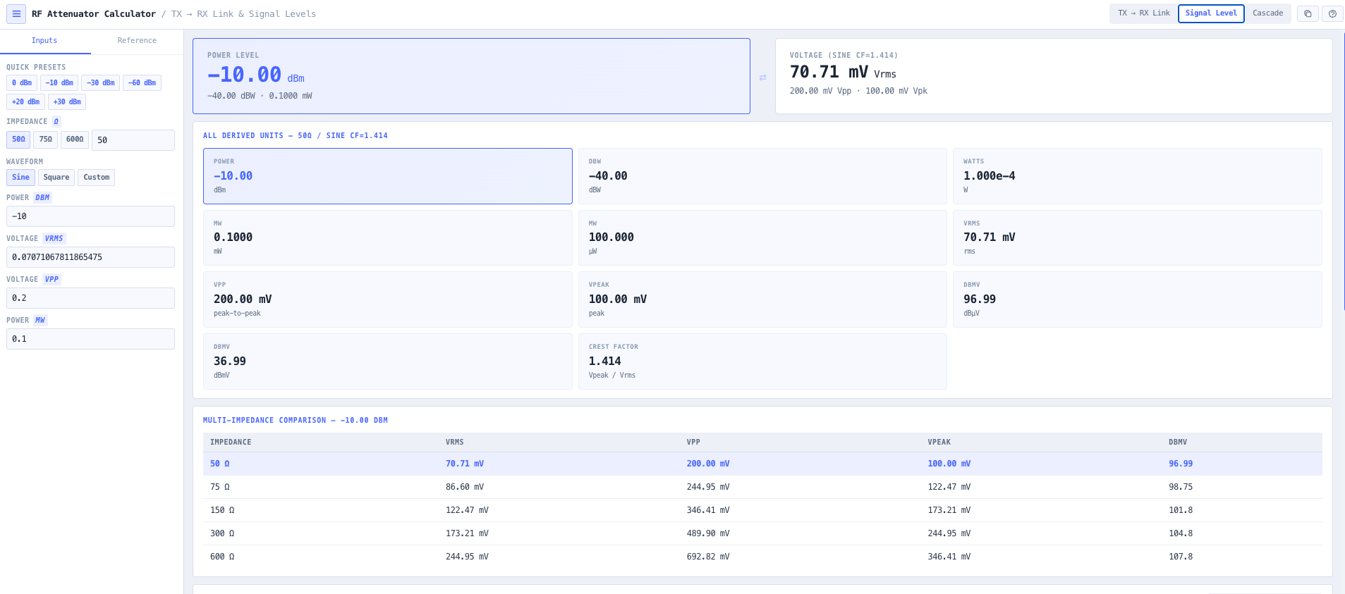
Convert between Vpp, Vrms, Vpeak, dBm, dBW, watts, microwatts, dBuV, and dBmV with full impedance awareness. 50 ohm system default with user defined impedance supported. Sine wave assumption applied to the Vpp to Vrms conversion (Vrms equals Vpp divided by 2 square root 2), with a configurable crest factor for square and arbitrary waveforms such as OFDM and pulsed carriers. All representations update simultaneously so the cross check between instruments is a glance rather than a calculation.
Required attenuation calculation
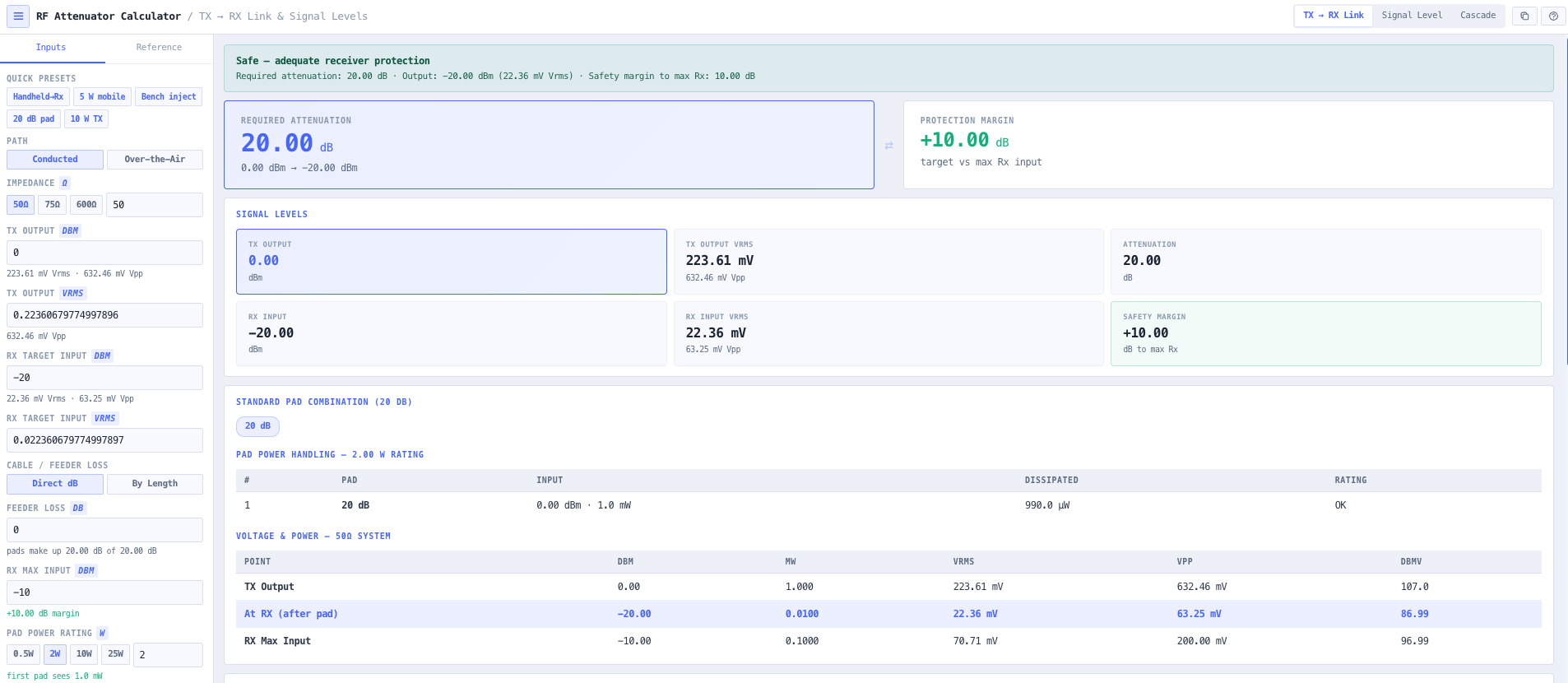
Compute the required attenuation in dB between any source and load. Input the source level as dBm or Vrms, the target level as dBm or Vrms, and the calculator resolves the required attenuation while preserving unit consistency. Useful for sizing the attenuator between a signal generator and a receiver, between an antenna source and a spectrum analyser front end, or anywhere two RF subsystems meet at incompatible levels.
Receiver protection and safety margin
Validates that the target level remains within the maximum safe input of the load. The protection margin in dB is reported explicitly. A warning fires when the target level exceeds the safe input threshold. Useful for protecting sensitive receiver front ends, ADC inputs, and lab instruments from accidental overdrive during commissioning and bench work.
Standard off the shelf pad combination
The required attenuation is decomposed into a combination of standard off the shelf attenuator pad values (30, 20, 15, 10, 6, 5, 3, 2, and 1 dB). A 47 dB target resolves to a deployable stack of standard inventory pads rather than a non standard custom part, and any fractional residual that cannot be made from standard pads is reported separately as a trim value. Useful for lab and field work where the available attenuator inventory is fixed.
Multi stage cascade builder
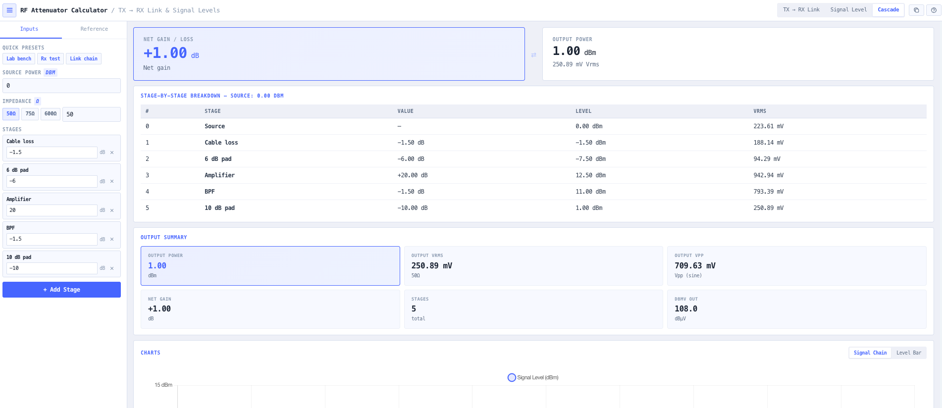
Build a chain of named stages from a configured source dBm. Each stage carries a name (for example Cable run, 10 dB pad, Filter, Amplifier) and a value in dB, entered as a negative number for a loss and a positive number for a gain. The result reports the level at every node from the source through to the end of the chain, the net gain, and the output level. Useful for checking a calibration chain, a test bench attenuator string, or a receiver protection cascade end to end.
Impedance awareness
50 ohm system default with user defined impedance supported. 75 ohm presets for video and CATV environments, 600 ohm for audio frequency and legacy telephony, and any custom impedance from 1 ohm to 10 kohm. The configured impedance is applied throughout the voltage and power conversions and the per node cascade voltage, so the result reflects the actual operating impedance rather than assuming 50 ohm.
Browser only computation
Runs entirely in your browser. No source levels, load specifications, or design data are submitted to a server. Useful for commercially confidential lab work, defence and intelligence test environments, and any setting where information security policy prohibits sending engineering data to third party services.
Inputs and outputs
What goes in, what comes out
Inputs 6
Source level in dBm or Vrms
Target level in dBm or Vrms
Maximum safe input level for receiver protection
System impedance in ohms (default 50)
Waveform or crest factor for non sinusoidal signals
Named stages with a dB gain or loss value for the cascade chain
Outputs 8
Source and target levels in dBm, watts, mW, Vpp, Vrms, Vpeak, and dBuV
Required attenuation in dB
Receiver protection margin in dB against the maximum safe input
Warning when the target level exceeds the safe input
Standard off the shelf attenuator pad combination with trim residual
Multi impedance comparison of the same power level
Per node level for the multi stage cascade chain
Result copied to the clipboard as plain text for test reports and hand over documents
Standards & methodology
IEEE 287. Precision coaxial connectors
50 ohm reference impedance for RF systems
dBuV referenced to 1 microvolt RMS (dBm equals dBuV minus 107 in 50 ohm)
Sine wave Vpp to Vrms conversion (Vrms equals Vpp divided by 2 square root 2)
Use cases
When to use this tool
01Protecting sensitive radio receiver inputs from high level signal generators
02Converting required Vpp input levels into dBm for RF signal generators
03Sizing the attenuator needed to drop a source level to a safe receiver input level
04Decomposing a required attenuation into a combination of standard off the shelf pads
05Injecting reference signals into receivers for sensitivity and adjacent channel testing
06Matching signal levels between RF subsystems
07Validating safe input levels during bench testing of receivers and amplifiers
08Checking a calibration chain of cable, pads, filters, and amplifiers end to end
09Producing a level plan for lab and field signal chain configurations
10Designing signal chains for non 50 ohm systems (cable TV at 75 ohm, custom impedances)
11Sanity checking signal level conversions between datasheet specifications and instrumentation readings
12Teaching RF lab technique fundamentals around level management and receiver protection
Power equals voltage squared divided by impedance for the RMS form. So in 50 ohm, a 1 Vrms signal is 20 mW (P equals 1 squared over 50 equals 0.02 W). In dBm, that is plus 13 dBm. Vpp converts to Vrms by Vrms equals Vpp divided by 2 square root 2 under the sine wave assumption. dBuV is referenced to 1 microvolt RMS, so 0 dBuV is 1 microvolt and the relationship to dBm in 50 ohm is dBm equals dBuV minus 107.
Does this design the resistor network inside an attenuator?
No. This tool treats an attenuator as a component you connect to a radio or a cable. It sizes the attenuation you need, checks it against the receiver safe input, and decomposes it into a combination of standard off the shelf attenuator pads. It does not compute Pi, T, or Bridged T resistor values for building an attenuator from discrete resistors, because that is circuit design rather than systems integration work.
How do I protect a receiver during sensitivity testing?
Sensitivity testing requires injecting a precisely known low level signal (typically minus 100 dBm or lower) into the receiver under test. The standard approach is a signal generator at a high reference level (for example minus 30 dBm) followed by a calibrated attenuator chain that drops the level to the test point. The calculator sizes the required attenuation, validates that the target level does not exceed the receiver safe input, and reports the protection margin for the test record.
What about non 50 ohm systems?
User defined impedance is supported. 75 ohm for cable TV and broadcast environments. Custom impedances for instrumentation, audio interfaces, and unusual RF systems. The calculator applies the configured impedance throughout the voltage and power conversions and the per node cascade voltage, so the result reflects the actual operating impedance rather than assuming 50 ohm.
How is the standard pad combination worked out?
A target total attenuation is decomposed into a deployable sequence of pads selected from a standard value set (30, 20, 15, 10, 6, 5, 3, 2, and 1 dB). For a 47 dB target the combination resolves to 30 plus 10 plus 6 plus 1 equals 47 dB. Any fractional residual that cannot be made from the standard set is reported separately as a trim value. Useful for lab and field work where the available pad inventory is fixed and a single exact value attenuator is not on hand.
How does this support EIRP and link budget work?
Attenuator and feeder loss feeds directly into the system loss term in an EIRP calculation, and into the feeder and miscellaneous loss line in a link budget. Use the Attenuator and Signal Level Calculator to size the attenuation and validate safe input. Carry the resulting loss into the noIM₃ EIRP Calculator for the radiated power, the Link Budget Calculator for full link feasibility, or the dB Conversion Calculator for general unit cross check.
Does any data leave my browser?
No. The calculator runs entirely in your browser. No source levels, load specifications, or design data are submitted to a server. Useful for commercially confidential lab work, defence and intelligence test environments, and any setting where information security policy prohibits sending engineering data to third party services.
Why does the sine wave assumption matter?
Vpp and Vrms differ by a factor that depends on the waveform. For a sine wave Vrms equals Vpp divided by 2 square root 2 (about 0.354 times Vpp). For a square wave Vrms equals Vpp over 2. For arbitrary waveforms the relationship depends on crest factor. The calculator applies the sine wave assumption by default and lets you override it with a square waveform or a custom crest factor so non sinusoidal cases (OFDM, pulsed) are not silently miscalculated.