What is the two ray ground reflection model?
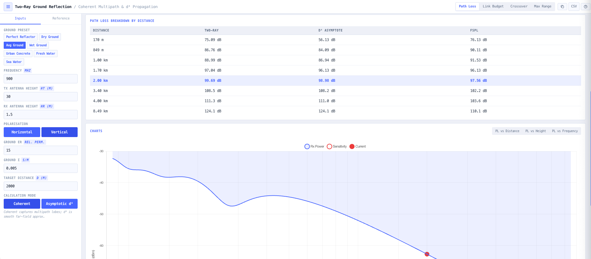
A propagation model that computes received power as the coherent sum of a direct line of sight ray and a single ground reflected ray. The two rays travel different path lengths and arrive at the receive antenna with a phase difference that depends on antenna heights, frequency, and distance. They sum coherently, producing constructive and destructive interference depending on the geometry. Close in, the result is multipath ripple. Beyond a crossover distance, the geometry stabilises into a smooth d to the fourth power path loss law.
When does the model apply?
When the link runs over relatively flat terrain or a smooth reflecting surface (open terrain, runways, airfields, water, low elevation cellular and land mobile geometries). It is the right model for low antenna communications where the ground reflected ray is a major contributor to the received signal. It is the wrong model for line of sight microwave with both antennas well clear of the ground (use FSPL or the noIM₃ Link Planner with full ITU P.530), and for dense urban environments (use the Log Distance Path Loss Calculator with an appropriate exponent).
What is the crossover distance and why does it matter?
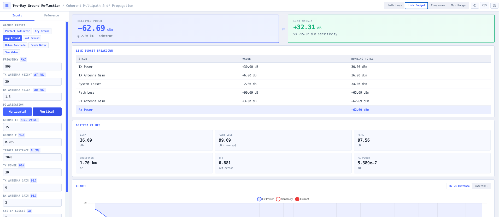
The crossover (break) distance dc equals 4 pi ht hr divided by lambda separates two regimes. Inside dc, the link sees free space loss plus multipath ripple from the direct and reflected ray interference. Beyond dc, the geometry stabilises and the path loss settles into a monotonic d to the fourth power roll off. For typical land mobile geometries (ht equals 30 m, hr equals 1.5 m, 800 MHz), dc is around 1.5 km. Inside that range you need the full coherent sum. Beyond it, the simpler d to the fourth formula is accurate.
Why does the far field path loss go as d to the fourth?
Because the direct and reflected rays arrive nearly out of phase at large grazing angles, the magnitudes of their electric fields nearly cancel. The residual is proportional to the path length difference, which itself decreases as 1 over d. The combined effect is that received power scales as 1 over d to the fourth power rather than 1 over d squared. This is purely geometric and does not depend on frequency, which is why the far field plane earth formula PL equals 40 log d minus 20 log ht minus 20 log hr is frequency independent.
How is the Fresnel reflection coefficient computed?
For horizontal (TE) polarisation, Gamma equals (sin theta minus square root of (epsilon r minus cos squared theta)) divided by (sin theta plus square root of (epsilon r minus cos squared theta)), where theta is the grazing angle and epsilon r is the complex relative permittivity (which folds in conductivity sigma). For vertical (TM) polarisation, Gamma equals (epsilon r times sin theta minus square root of (epsilon r minus cos squared theta)) divided by (epsilon r times sin theta plus square root of (epsilon r minus cos squared theta)). Built in presets cover dry ground, wet ground, fresh water, sea water, urban concrete, and perfect reflector.
How does polarisation choice affect the result?
Horizontal polarisation has Gamma close to minus 1 at low grazing angles regardless of ground type, which produces strong multipath ripple and deep nulls. Vertical polarisation passes through a Brewster angle minimum where Gamma is close to zero and the reflected ray contribution drops, which can soften the multipath behaviour. The polarisation choice matters most over water and at low grazing angles, where the difference between H and V is large. The calculator handles each polarisation separately.
How is this different from FSPL and the Log Distance Path Loss model?
FSPL assumes a single direct ray and is correct for free space and short line of sight links above the ground. The Log Distance Path Loss model is empirical and uses a tunable exponent n to fit measured environment behaviour. The Two Ray model is physically based, accounts explicitly for the ground reflected ray, and predicts the d to the fourth far field law from first principles. Use FSPL for free space. Use the Two Ray model for terrestrial low antenna geometries over flat ground or water. Use the Log Distance model when the environment is too complex for two ray and you have measured calibration data.
Does any data leave my browser?
No. The calculator runs entirely in your browser. No transmit power, antenna height, or path data is submitted to a server. Useful for commercially confidential coverage planning, defence and naval communications, and environments where information security policy prohibits sending engineering data to third party services.