Antenna Utilities

Antenna Separation Calculator

Co-location antenna isolation and physical separation for RF systems integration. Solve horizontal, vertical, and slant separation for a target isolation, budget the required isolation from desense and blocking, compare geometries, size filtering, and check a whole tower layout.

Free forever on a Standard account. No credit card.

Overview

Put two antennas on the same tower or rooftop and they couple to each other. When one is transmitting and the other receiving, that coupling can desensitise or block the receiver, and the fix is separation: the antennas have to be far enough apart that the isolation between them holds the interference below what the receiver can tolerate. The question every co-location engineer asks is simply how far, and the answer depends heavily on whether the antennas are side by side or stacked.

The noIM₃ Antenna Separation Calculator sizes that separation with the standard first-order co-siting isolation laws. Horizontal separation, antennas side by side, gives an isolation of 22 + 20·log₁₀(d/λ) less the two antenna gains, rising 20 dB per decade. Vertical separation, antennas stacked so they sit in each other pattern nulls, gives 28 + 40·log₁₀(d/λ), rising 40 dB per decade, which is why a few metres of vertical stacking can beat many metres of horizontal spacing. Slant separation, an antenna offset both ways, is interpolated between the two by the elevation angle. It is a systems integration tool, not an antenna design tool: the gains and the required isolation are inputs.

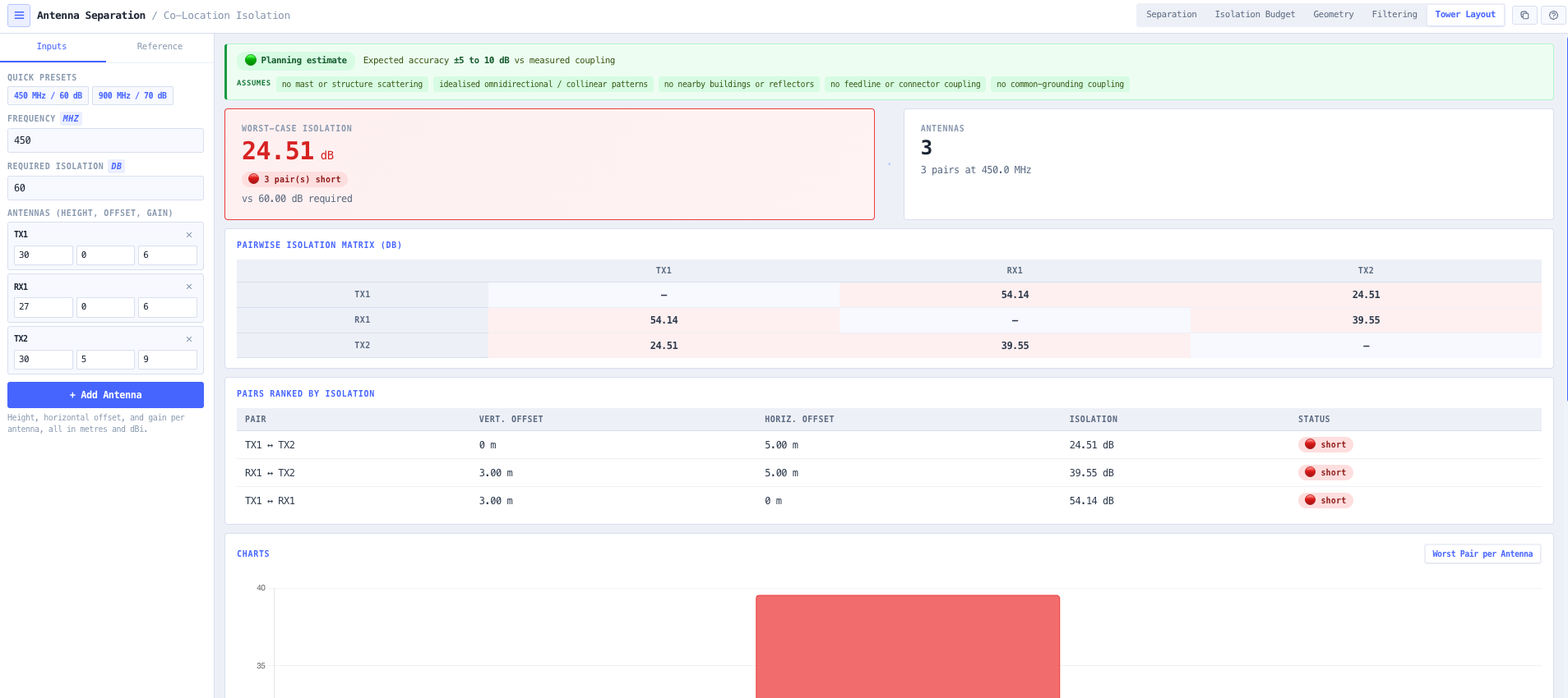
Five modes cover the co-location job end to end. Separation solves the spacing for a required isolation or the isolation for a spacing. Isolation Budget works out how much isolation you actually need from the interference scenario, receiver desense and receiver blocking. Geometry compares the separation each geometry needs so the vertical stacking saving is explicit. Filtering sizes the extra duplexer or cavity isolation when the available separation falls short. Tower Layout resolves a set of antennas by height and offset into a pairwise isolation matrix, flagging the problem pairs.

Capabilities

Separation for a target isolation, or isolation for a spacing

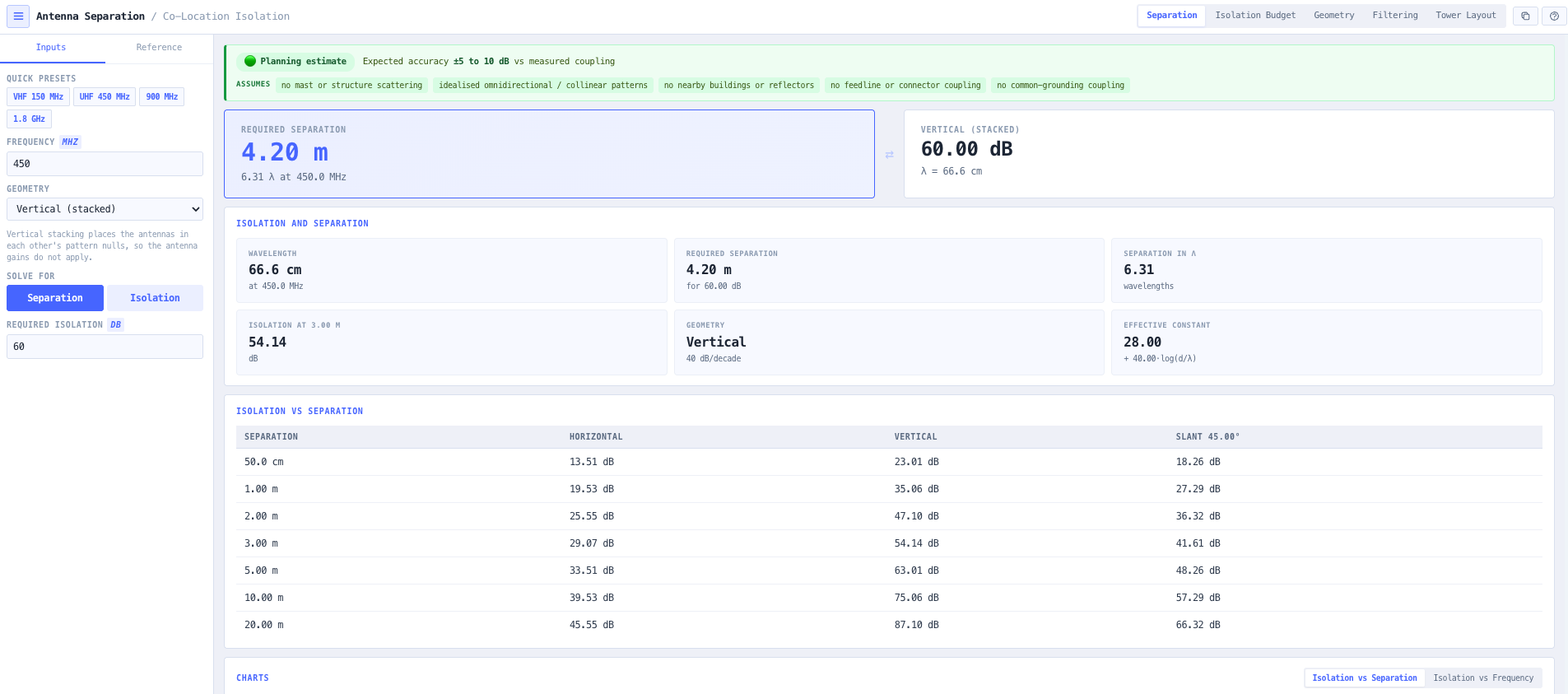
Enter the frequency and geometry and solve the minimum spacing two co-located antennas need for a required isolation, reported in metres and wavelengths, or switch to read the isolation an existing spacing achieves. Horizontal, vertical, and slant geometries are all supported.

The co-siting isolation laws

Horizontal isolation is 22 + 20·log₁₀(d/λ) − Gₜ − Gᵣ, rising 20 dB per decade. Vertical isolation is 28 + 40·log₁₀(d/λ), rising 40 dB per decade because the antennas sit in each other pattern nulls. Slant is interpolated between the two by the elevation angle of the line joining the antennas.

Vertical stacking made explicit

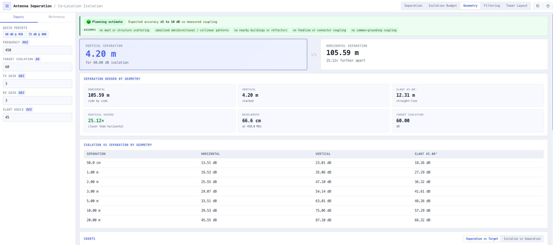
Because the vertical law rises twice as fast, stacking reaches a target isolation in a fraction of the horizontal distance. The Geometry mode reports the separation horizontal, vertical, and slant each need for one target and states the vertical saving directly, so the layout decision is quantified rather than assumed.

How much isolation you actually need

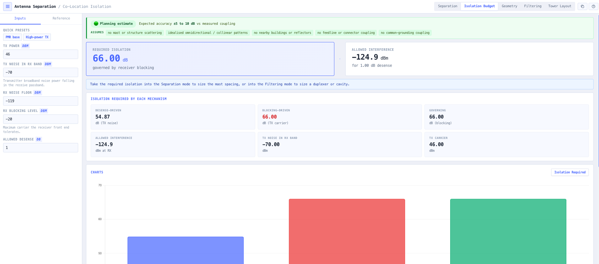
A separation is only meaningful against a requirement. The Isolation Budget mode computes the isolation each interference mechanism demands: receiver desense from transmitter noise falling in the receive band, and receiver blocking from the transmitter carrier, and reports the governing one.

Desense turned into a tolerable interference level

A given desensitisation corresponds to a specific interfering power relative to the receiver noise floor: a 1 dB desense to an interferer about 6 dB below the floor, a 3 dB desense to one equal to the floor. The tool computes the tolerable interference and the isolation needed to reach it, so the trade between allowed degradation and required isolation is visible.

Separation against filtering on a constrained site

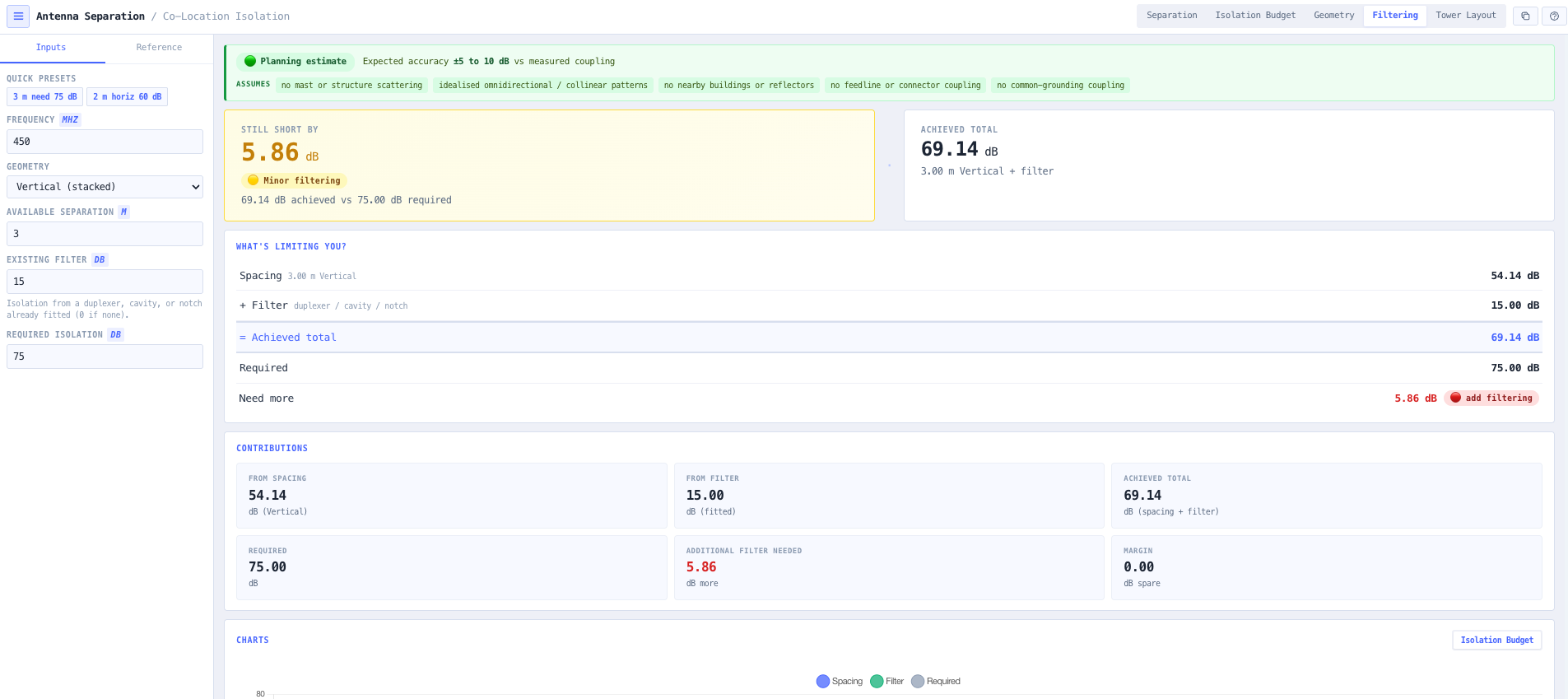
When there is not enough room, the shortfall is made up with filtering. The Filtering mode takes the separation actually available, reports the isolation it achieves, and reports the extra duplexer, cavity, or band-reject isolation needed to close the gap, colour coded from sufficient separation to heavy filtering.

Whole-tower layout matrix

The Tower Layout mode takes a set of antennas by height, horizontal offset, and gain and resolves them into a pairwise isolation matrix, colouring every pair pass or fail against the requirement, calling out the worst-case pair, and ranking the pairs so the antennas that need to move or be filtered are obvious.

Browser only computation

Runs entirely in your browser. No frequencies, separations, or site layouts are submitted to a server. Useful for commercially confidential work, classified projects, or any environment where information security policy prohibits sending engineering data to third party services.

Standards & methodology

  • Horizontal co-siting isolation 22 + 20·log₁₀(d/λ) − Gₜ − Gᵣ, where 22 dB is the free-space path loss in wavelengths
  • Vertical co-siting isolation 28 + 40·log₁₀(d/λ) for vertically polarised collinear antennas
  • Slant isolation interpolated between the horizontal and vertical laws by the elevation angle
  • Tolerable interference for a desense of Δ dB set at 10·log₁₀(10^(Δ/10) − 1) relative to the receiver noise floor
  • Free-space wavelength λ = 300 / f(MHz) metres

When to use this tool

  • Sizing the physical separation two co-located antennas need for a target isolation
  • Reading the isolation an existing antenna spacing achieves
  • Deciding whether to stack antennas vertically or spread them apart horizontally
  • Quantifying how much closer vertical stacking can be than horizontal spacing
  • Working out how much isolation a co-location actually requires from the interference scenario
  • Sizing the isolation needed to hold receiver desense within an allowed budget
  • Sizing the isolation needed to keep a transmitter carrier below the receiver blocking level
  • Sizing the duplexer or cavity filtering needed when the available separation falls short
  • Checking a whole tower or rooftop layout for pairs below the required isolation
  • Finding the worst-case antenna pair on a busy structure
  • Comparing co-location separation requirements across VHF, UHF, and microwave bands
  • Teaching antenna-to-antenna isolation and the vertical stacking advantage

Is this the right tool for you?

Reach for the Antenna Separation Calculator in any of the following situations.

  • You are adding a UHF base antenna to a tower that already carries a receiver and need the vertical separation for 60 dB of isolation.
  • You have 3 m of vertical space on a mast and want to know whether that is enough isolation at 450 MHz or whether you need a filter.
  • You are choosing between spreading two antennas 10 m apart on a rooftop or stacking them 3 m up a pole and want the isolation each gives.
  • You have a 46 dBm transmitter with a −70 dBm noise floor in the receive band and need the isolation to hold a 1 dB desense on a nearby receiver.
  • You need to keep a strong transmitter carrier below a receiver −20 dBm blocking level and want the isolation that requires.
  • You have less separation than the co-location needs and want to know how much duplexer or cavity filtering closes the gap.
  • You are laying out six antennas on one tower and want the pairwise isolation matrix to find which pairs are too close.
  • You are auditing an existing co-location that is causing interference and want to check the isolation between the offending antennas.
  • You are comparing the separation a 150 MHz system needs against a 900 MHz system for the same isolation.
  • You are writing a co-location plan and need the required isolation and the separation to justify the mast layout.
  • You are training junior engineers on why stacking antennas vertically is so much more space efficient than spreading them apart.
  • You are operating under a security regime that prohibits sending design data to third party services and need a calculator that runs entirely in your browser.

Frequently asked questions

How far apart do co-located antennas need to be?

It depends on the required isolation, the frequency, and whether the antennas are side by side or stacked. Horizontal separation gives an isolation of 22 + 20·log₁₀(d/λ) less the antenna gains, so reaching 60 dB at 450 MHz side by side takes on the order of tens of wavelengths. Vertical stacking gives 28 + 40·log₁₀(d/λ), so the same 60 dB is reached in a few wavelengths. The calculator solves the exact distance for your frequency, geometry, and required isolation.

Why is vertical separation so much more effective than horizontal?

Because of the antenna patterns. Antennas mounted side by side point their main beams at each other in azimuth, so the coupling is high and falls off relatively slowly at 20 dB per decade. Antennas stacked vertically sit in each other pattern nulls, where the radiation is weak, so the coupling starts lower and falls off twice as fast at 40 dB per decade. The result is that a few metres of vertical separation can achieve what tens of metres of horizontal spacing would, which is the single most useful fact in co-location layout.

How much isolation do I actually need?

Enough to hold the interference below what the receiver tolerates, and that comes from two mechanisms. Receiver desense is the transmitter broadband noise falling in the receive band raising the noise floor; the isolation must bring that noise below the level that would degrade the receiver by more than the allowed amount, typically 1 dB. Receiver blocking is the transmitter carrier overloading the front end; the isolation must keep the carrier below the blocking level. The Isolation Budget mode computes both from your transmitter and receiver figures and reports the larger, governing requirement.

What does a 1 dB desense correspond to?

An interfering power about 5.9 dB below the receiver noise floor. Desensitisation is how much the interference raises the effective noise floor: an interferer equal to the floor adds 3 dB, an interferer 6 dB below adds about 1 dB, and so on. So allowing 1 dB of desense means the transmitter noise reaching the receiver must sit almost 6 dB under its noise floor, and the required isolation is whatever brings the transmitter noise down to that level. The calculator does this conversion for any allowed desense.

What if I do not have enough room for the separation?

Make up the shortfall with filtering. A bandpass cavity, a band-reject notch, a duplexer, or a ferrite isolator adds isolation on top of the physical separation. The Filtering mode breaks the isolation into its contributions and stacks them: the spacing provides one part, any filter already fitted provides another, and the two together are compared against the requirement. So if 3 m of vertical separation gives 54 dB and a fitted cavity adds 15 dB, the achieved total is 69 dB, which the tool shows is 6 dB short of a 75 dB requirement rather than only telling you the raw filtering figure. Breaking the budget down this way makes it far easier to reason about what is limiting you and how much more filtering to buy.

Can I check a whole tower at once?

Yes. The Tower Layout mode takes a set of antennas, each with a height, a horizontal offset, and a gain, and computes the isolation between every pair using the appropriate horizontal, vertical, or slant law. The result is a pairwise isolation matrix with every pair coloured pass or fail against the requirement, the worst-case pair called out, and the pairs ranked, so you can see at a glance which antennas on a busy structure are too close.

How accurate are these figures?

They are standard first-order far-field estimates, typically good to within about 5 to 10 dB of measured antenna-to-antenna coupling in benign conditions, and worse where there is significant scattering. They are excellent for sizing a mast, comparing geometries, and finding the problem pairs, but they ignore mast and structure scattering, near-field effects at very close spacing, the detailed antenna patterns, nearby buildings and reflectors, feedline and connector coupling, and common-grounding effects, and the vertical form assumes vertically polarised collinear antennas. A prominent planning-estimate confidence indicator carries the expected accuracy and these assumptions on every screen. For a critical or marginal installation, confirm the number with measured coupling or a full electromagnetic model.

Does any data leave my browser?

No. The calculator runs entirely in your browser. No frequencies, separations, or site layouts are submitted to a server. Useful for commercially confidential work, classified projects, or environments where information security policy prohibits sending engineering data to third party services.