RF Utilities

RF Filter & Combining Designer

Shared site RF plumbing workstation, deciding which radios share an antenna, what filtering that decision requires, and what the filtering costs in transmit power and receive sensitivity before any hardware is quoted.

Included in the 14-day Pro trial on every new account. No credit card.

Overview

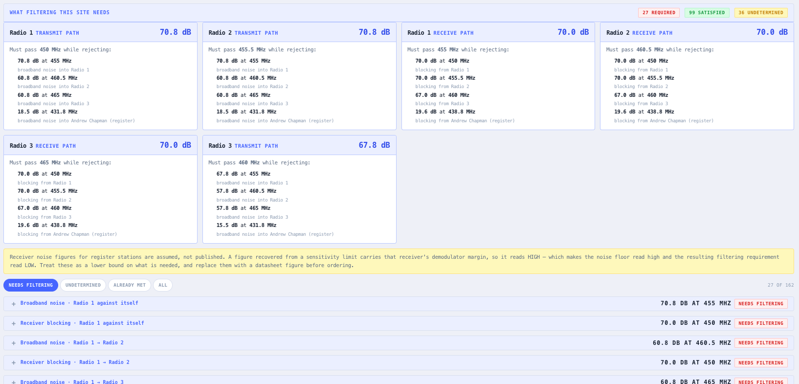
Most integrators know they have an interference problem long before they know what to do about it. A co-siting study or a desense calculation will tell you that you are twenty three decibels short. Neither tells you that closing that shortfall takes a two cavity pass notch at a four and a half megahertz offset, or that the assembly which closes it costs more in transmit power and receive sensitivity than the interference did. This tool is the second half of that conversation.

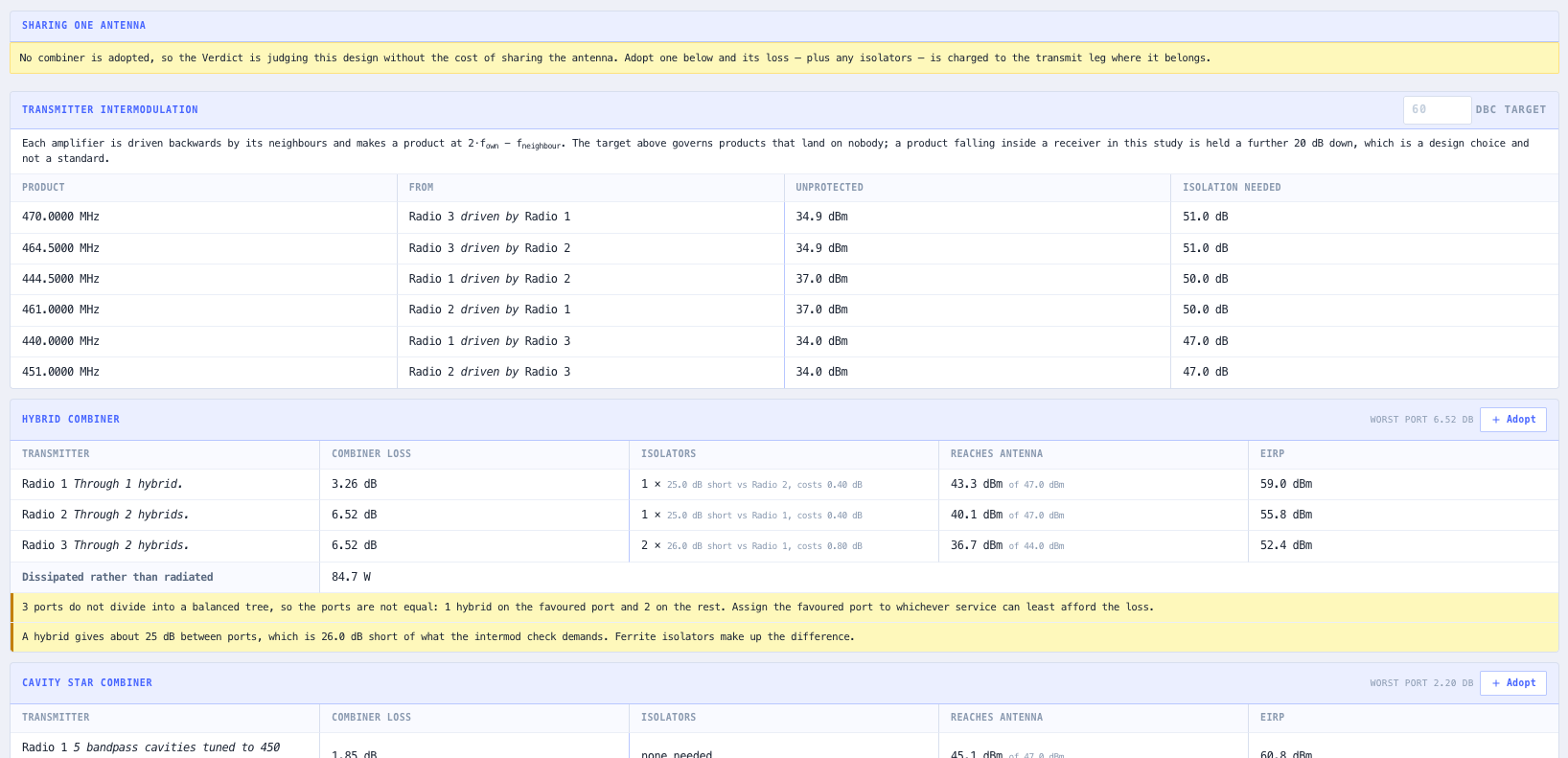
The unit of work is a site, not a filter. Radios and antennas are recorded first, and the plumbing decision, which radios share which antenna, is the input that creates a filtering requirement in the first place. A single antenna carrying both a transmitter and a receiver needs a duplexer. Several transmitters onto one antenna need a combiner, and whether that is a low loss cavity star or a hybrid paying three decibels per doubling depends on how far apart the channels are. Several receivers off one antenna need a multicoupler, and the trap there is a preamplifier whose gain wrecks the dynamic range at a busy site.

The cavity mathematics is deliberately small and deliberately honest. Two relations, the resonator skirt from loaded Q and the insertion loss from the ratio of loaded to unloaded Q, contain the entire trade of the domain: tighten the coupling and you buy selectivity with loss, every time, with no setting that gives it away free. Cavity size and band set the unloaded Q, and cascading cavities stacks both the rejection and the cost. Results are planning grade and labelled as such. A real cavity departs from the ideal resonator through higher order modes, temperature drift and case leakage, and a cascade total assumes a harness phased well enough to keep the cavities from interacting, which vendors tune for and which a design must not assume for free.

Capabilities

Site level study, not a single filter

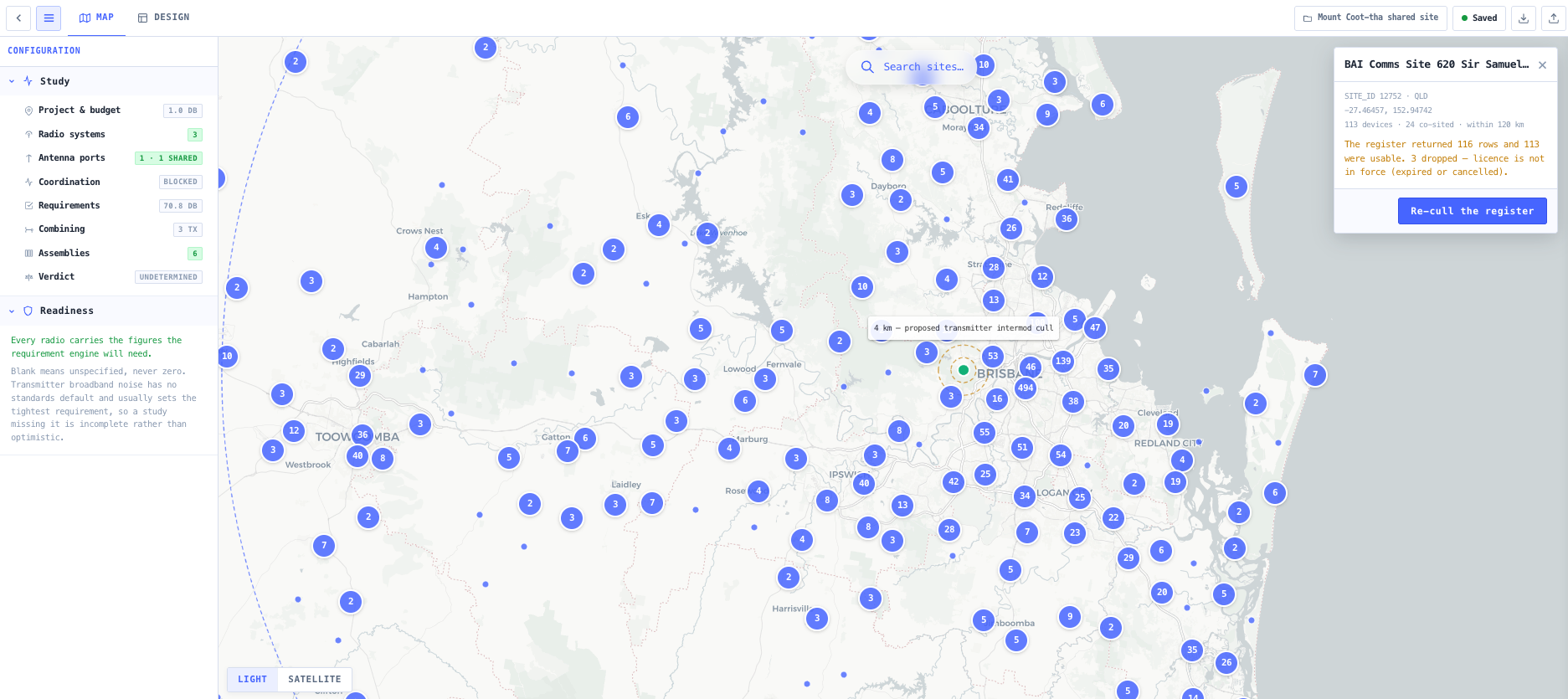
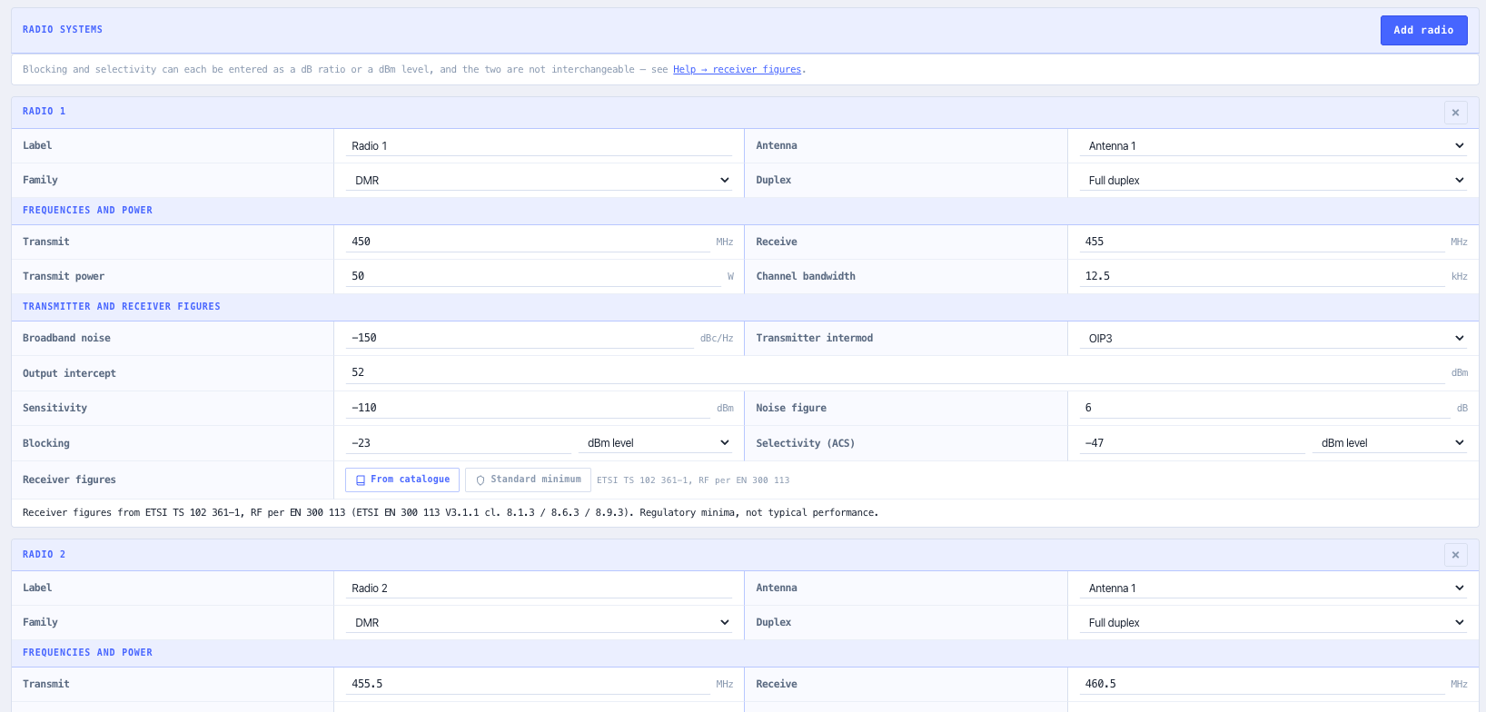
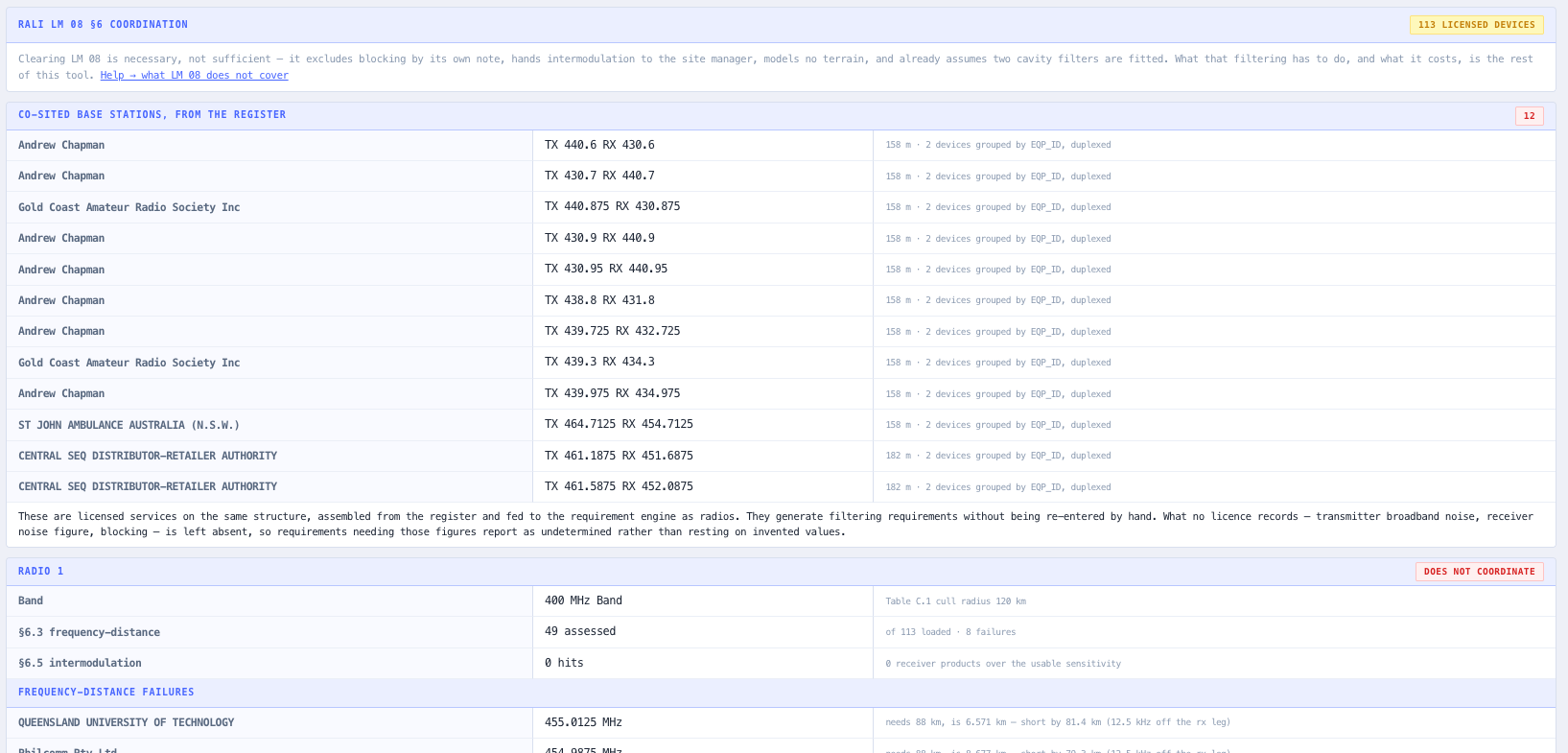
Every radio and antenna at the site is recorded, including co-sited services you do not own, because those are the ones that make the requirement. The study holds the whole site so a filtering decision is taken against the real carrier set rather than against one pair of frequencies in isolation.

Antenna sharing as an explicit decision

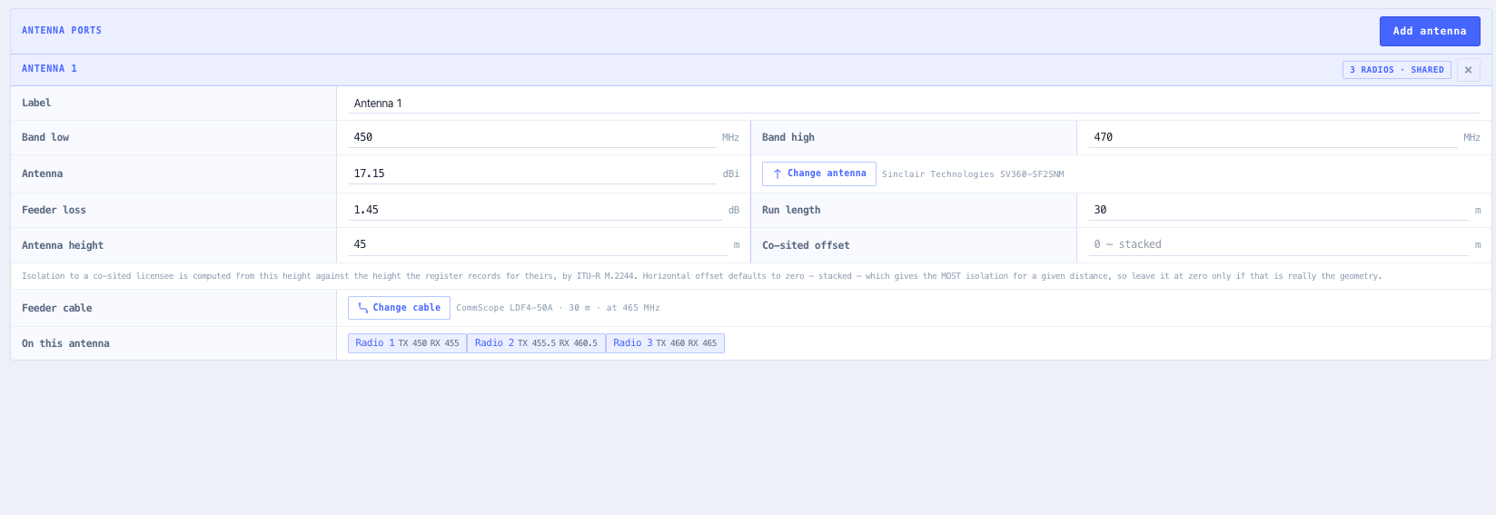
Which radios share which antenna is an input rather than an assumption, because sharing is exactly what creates a duplexer, combiner or multicoupler requirement. Change the sharing and the requirement changes with it, which is the cheapest lever available before any hardware is priced.

Bandpass cavity response from resonator physics

Cavity response is derived from loaded and unloaded Q, with the flat insertion loss at resonance kept separate from the skirt. That separation is the point: the rejection an assembly achieves and the loss it costs come out of the same two relations, so you can never quietly buy selectivity without paying for it.

Band reject cavities specified the way a datasheet quotes them

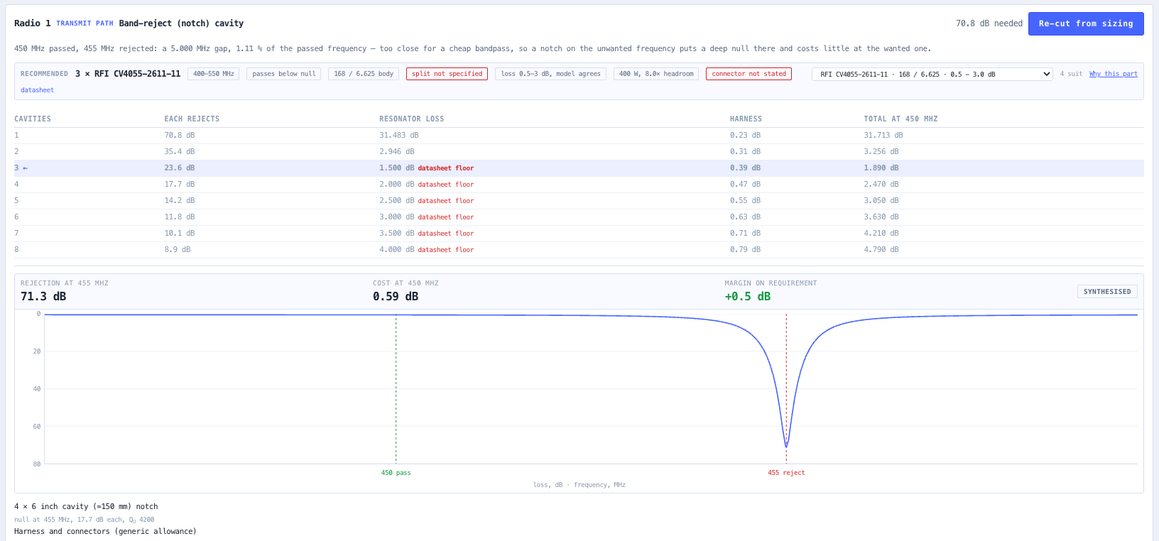
Band reject response is derived from a shunt series resonant branch and specified by the notch depth a datasheet actually states, so the cost at the pass frequency falls out of the physics rather than an interpolation between two catalogue numbers.

Cascade evaluation at both frequencies at once

A chain is evaluated at the reject frequency and the pass frequency together, because a cascade that closes the shortfall and eats four decibels of transmit power is a different proposition from one that closes it and eats one. Stacking cavities stacks both numbers, and the tool shows them side by side.

Per figure trust grading

Every figure is graded measured, synthesised, or extrapolated beyond the span a vendor actually swept. Vendor measured response curves override synthesis wherever a real sweep exists, so a study states which of its numbers rest on a measurement and which are model output.

Receiver limits kept in the units the standard states

Receiver susceptibility is captured in the form its standard uses, a ratio in decibels or an absolute level in dBm, and never silently converted between the two. The standards genuinely disagree on this, and forcing them into one unit system loses information the design needs.

Blank means unspecified, never zero

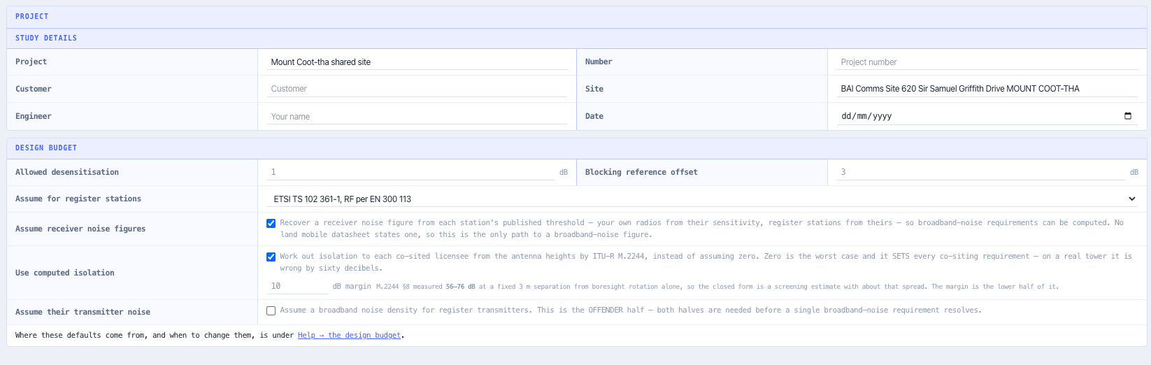
A field nobody has filled in is reported as a gap rather than defaulted to a number that makes the study look complete. A filtering study with holes in it should say so, because an assumed zero is the fastest way to a confident answer that is wrong.

Standards & methodology

  • ETSI EN 300 086 and EN 300 113 receiver susceptibility limits, cited where used
  • ITU-R SM.1134 intermodulation arithmetic, cited where used
  • Topology selection guidance is engineering practice drawn from resonator theory and manufacturer application notes, and is presented as practice rather than as a rule with a clause number behind it

When to use this tool

  • Deciding whether two services can share one antenna, or need separate ones
  • Sizing the duplexer for a repeater before asking a vendor to quote it
  • Working out what a combiner costs in transmit power before committing to a shared antenna
  • Checking whether a proposed filter assembly closes a co-siting shortfall or merely dents it
  • Diagnosing a shared site that is already built and desensing, where nobody documented the plumbing
  • Comparing a cavity star combiner against a hybrid for a tightly spaced channel group
  • Explaining to a client why the cheap assembly costs them coverage
  • Teaching apprentices what a cavity, a notch and a duplexer actually do, and when each is required

Is this the right tool for you?

Reach for the RF Filter & Combining Designer in any of the following situations.

  • Size a duplexer for a repeater sharing one antenna between transmit and receive
  • Compare a cavity star combiner against a hybrid for a tightly spaced channel group
  • Check whether a proposed cavity assembly closes a co-siting isolation shortfall
  • Model what a multicoupler costs a busy receive site in dynamic range

Frequently asked questions

Is this a filter design tool?

No. It does not synthesise a coupling matrix, dimension an iris, or produce a manufacturable cavity. It specifies a requirement and predicts the response of a class of assembly, so you know what to ask for and what it will cost you before anyone quotes it. A vendor still designs and tunes the actual part.

How accurate are the predicted responses?

Planning grade, and the tool says so rather than implying otherwise. The single resonator model is exact for an ideal resonator and approximate for a real cavity, which departs from the ideal through higher order modes, temperature drift and case leakage. A cascade total also assumes a harness phased well enough to keep the cavities from interacting, which is something vendors tune for and a design must not assume for free. None of this replaces a network analyser sweep of the tuned article.

Which standard governs filter selection?

None does, and it would be misleading to suggest otherwise. The receiver susceptibility limits come from ETSI EN 300 086 and EN 300 113, and the intermodulation arithmetic from ITU-R SM.1134, and those are cited where they are used. The topology selection guidance, when a cavity star beats a hybrid and when a notch is enough, is engineering practice drawn from resonator theory and manufacturer application notes. It is presented as practice, not as a rule with a clause number behind it.

Why is insertion loss treated as seriously as rejection?

Because it is the half of the trade that gets forgotten. Tightening the coupling to buy selectivity always costs loss, and the loss lands on transmit power and receive sensitivity, which is coverage. An assembly that closes a twenty three decibel shortfall while eating four decibels of transmit power may cost more than the interference did. Evaluating the chain at the reject and pass frequencies together is what makes that visible before anything is bought.

Does it produce a filter schedule or a specification document?

No, and this is out of scope rather than pending. The tool holds a study, derives requirements, advises on topology, sizes an assembly and returns a verdict, and all of that is on screen. There is no filter schedule, block diagram, specification for quotation or PDF export.

What happens when a figure is missing?

It is reported as unspecified. A blank field is never treated as zero, and a study with gaps in it reports them rather than quietly assuming values that make the result look complete. Every figure that is present carries a grade saying whether it was measured, synthesised, or read outside the span a vendor actually swept.

How does this relate to a co-siting study?

A co-siting study tells you how short you are. This tells you what closes the gap and what closing it costs. The two are the same conversation: separation and filtering are the two levers available on a shared site, and the cheapest answer is often a different sharing decision rather than more hardware, which is why the sharing decision is an explicit input here.