Overview
What the Fibre Optic Connector and Splice Loss Calculator does
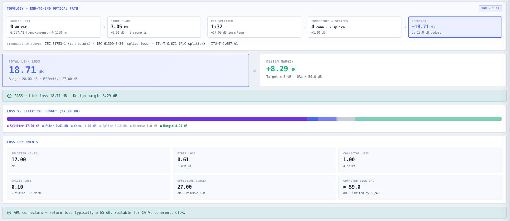
A fibre link either closes inside its loss budget or it does not, and the difference is often a few tenths of a dB spread across connectors, splices and kilometres of cable. The budget comes from a physical inventory: feeder, distribution and drop segments with their own attenuation at the operating wavelength, a mix of APC and UPC connectors, fusion and mechanical splices that behave quite differently, and perhaps a PON splitter that takes a large share on its own. Adding it up by hand is slow and easy to get wrong.
Read the full overview
The calculator builds the budget the way the plant is built. Each fibre segment has its own length and attenuation, filled in from the selected fibre type and wavelength and editable when you have cable data or OTDR results. Connectors are entered by type and number of mated pairs at the TIA-568.3-E maximum of 0.75 dB, and fusion and mechanical splices are counted separately at 0.30 dB, each editable with manufacturer or measured values. An optional PLC splitter adds the ITU-T G.671 maximum insertion loss for the chosen split ratio, or the manufacturer's figure.
The total link loss is compared with the maximum allowable loss less any ageing and contamination allowance you enter, and the design margin passes at 0 dB or more, or is flagged when it falls under a target you set. No standard gives a value for the allowances or the target, so they are blank by default. A worst-case link return loss is calculated from the TIA minimum return loss of every connection and splice, and the limiting item is named. When a multimode fibre is selected at 850 nm, the span and link loss are also checked against IEEE 802.3 short reach Ethernet limits, because modal dispersion can limit reach even when the loss budget closes.