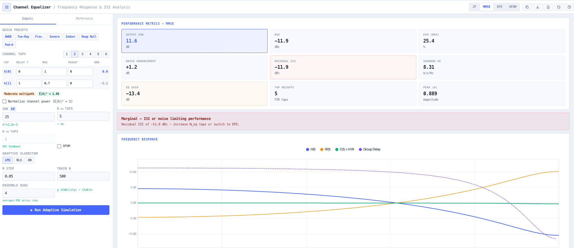
Zero Forcing, MMSE, and Decision Feedback equaliser design with adaptive LMS, RLS, and decision directed simulation. Frequency and impulse response visualisation, eye diagram, ISI analysis, and standards compliance against LTE, 5G NR, DVB T2, WiFi 6, and DOCSIS 3.1.
Top bar with the four equaliser modes (ZF, MMSE, DFE, OFDM) and the Inputs versus Reference panel tabs.
Overview
What the Channel Equalisation Calculator does
Real RF channels are not flat. Multipath reflections from buildings, terrain, and vehicles produce frequency selective fading where some frequencies arrive at full strength while others fall into deep nulls. The result on a wideband digital signal is inter symbol interference (ISI), where each transmitted symbol smears into its neighbours and the receiver cannot decide which symbol was sent. The fix is channel equalisation. The receiver estimates the channel impulse response and applies a filter that compensates the distortion before symbol decisions are made. The classical equaliser families (Zero Forcing, MMSE, Decision Feedback) trade off ISI cancellation, noise enhancement, and complexity differently, and choosing between them is one of the foundational decisions in modem and receiver design.
Read the full overview
The noIM₃ Channel Equalisation Calculator is a complete design and visualisation workbench for these structures. Define a channel from up to six multipath taps, each with independent delay (fractional symbol periods are handled via exact sinc interpolation in the frequency domain), magnitude, and phase. Built in presets cover AWGN, two ray, indoor multipath, severe multipath, deep spectral null, and the ITU Pedestrian A reference. The calculator solves the equaliser tap weight problem in the frequency domain and presents Zero Forcing, MMSE, and Decision Feedback Equaliser results simultaneously so the trade off is visible rather than buried.
Output covers the metrics that actually matter for receiver design. Output SNR per equaliser type derived analytically. MMSE per subcarrier MSE equals sigma squared divided by (magnitude H squared plus sigma squared). EVM equals square root of MSE times 100 per cent. Noise enhancement quantifies the SNR penalty Zero Forcing pays at spectral nulls. Residual ISI measures interference left after equalisation. Shannon spectral efficiency provides the theoretical capacity bound for the current channel. Standards compliance is checked in real time against LTE, 5G NR FR1 with 1024 QAM, DVB T2, WiFi 6, and DOCSIS 3.1. An adaptive simulation engine trains a BPSK equaliser using LMS, RLS, or decision directed mode and plots MSE versus training symbol on a dB scale so step size and forgetting factor can be tuned for the channel and convergence requirement.
Capabilities 9
Zero Forcing, MMSE, and DFE simultaneously
All three primary linear and semi linear equaliser structures computed simultaneously from the same channel and SNR inputs. Zero Forcing inverts the channel completely (ideal at high SNR, problematic at spectral nulls). MMSE balances ISI and noise (optimal at any SNR, the standard choice). DFE adds an IIR feedback filter to cancel post cursor ISI from past decisions (approaches the Shannon bound on severe multipath). The trade offs are visible side by side rather than requiring three separate calculations.
Fractional delay multipath channel model
Up to six multipath taps, each with independent delay (fractional symbol periods handled via exact sinc interpolation in the frequency domain), magnitude in dB or linear, and phase in degrees. Channel transfer function H[k] equals sum over n of h[n] times exp of (minus j 2 pi k tau[n] divided by N), evaluated across 256 frequency points. Built in presets for AWGN, two ray, indoor, severe, deep spectral null, and the ITU Pedestrian A reference channel.
Real time output metrics
Output SNR per equaliser type. MMSE per subcarrier MSE equals sigma squared divided by (magnitude H squared plus sigma squared), averaged across the band. EVM equals square root of MSE times 100 per cent, mapping directly to standards test requirements. Noise enhancement (the SNR penalty Zero Forcing pays at spectral nulls) reported separately. Residual ISI in dB. Shannon spectral efficiency C equals (1 over N) sum log base 2 of (1 plus SNR times magnitude H squared) for theoretical capacity reference.
Adaptive LMS, RLS, and decision directed simulation
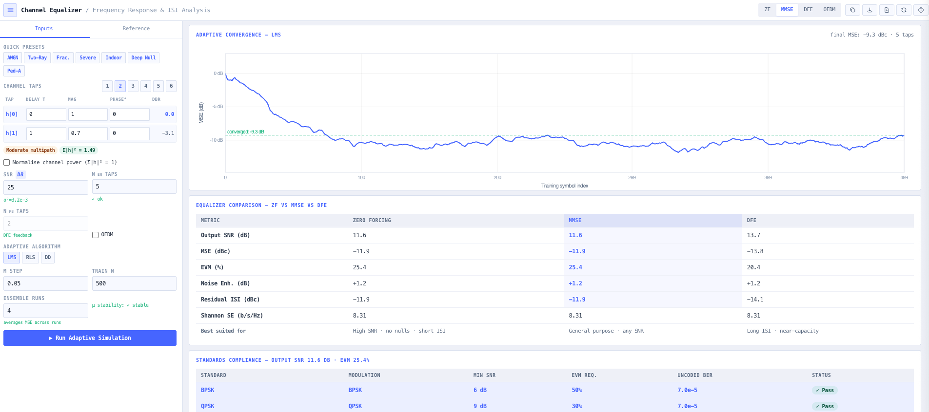
Train a BPSK equaliser over a configurable number of symbols using Least Mean Squares (configurable step size mu), Recursive Least Squares (configurable forgetting factor lambda), or decision directed mode. Convergence plotted as MSE versus training symbol on a dB scale. Final converged MSE reported. RLS converges dramatically faster than LMS at the cost of O(N squared) per symbol complexity, useful for fast fading or short burst scenarios.
Frequency and impulse response visualisation
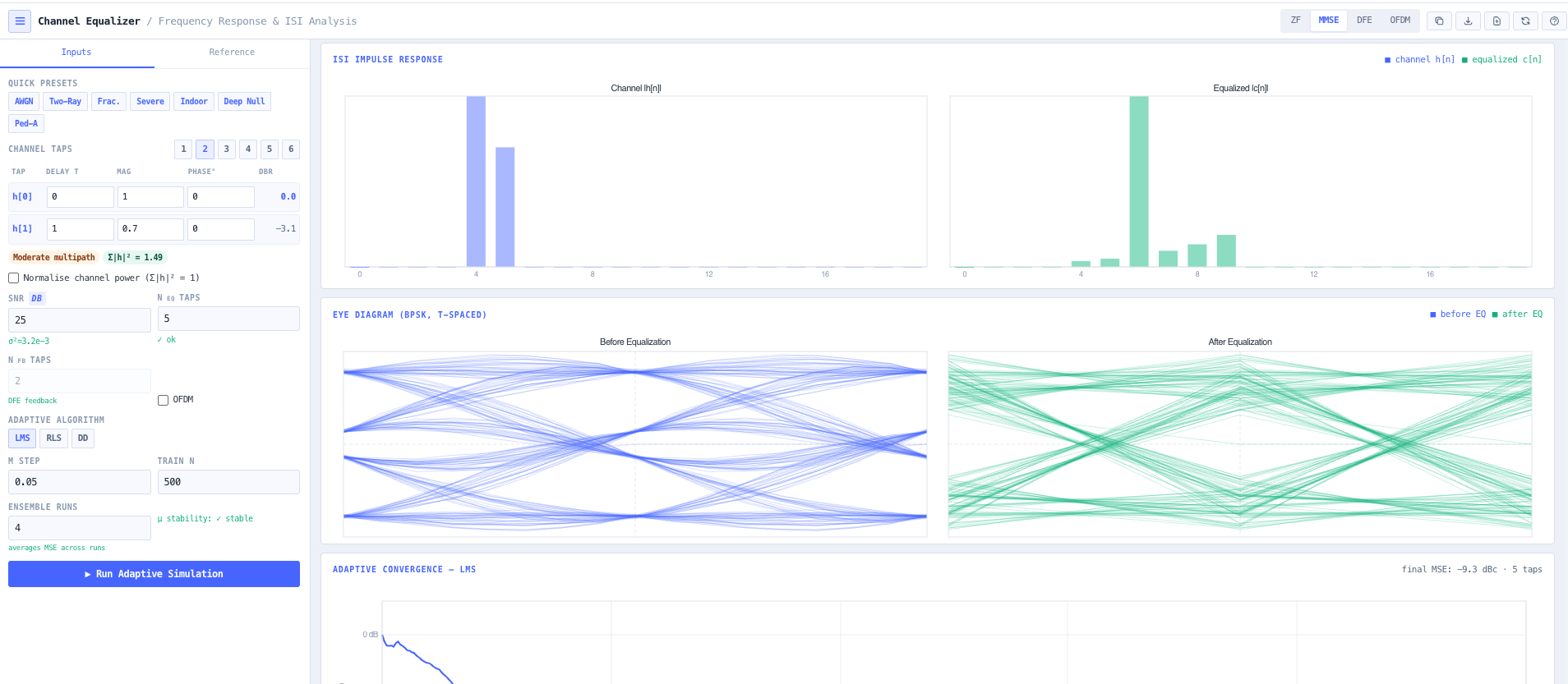
Channel response, equaliser response, combined response, and group delay plotted across normalised frequency 0 to 0.5. Equaliser tap weights as a bar chart. ISI impulse response plot showing the channel and equalised pulse shape. Eye diagram comparing before and after equalisation. DFE block diagram for the decision feedback case. Together they cover the full visual story of what the equaliser is doing.
OFDM per subcarrier equalisation
OFDM mode switches to per subcarrier frequency domain MMSE equalisation. W[k] equals H conjugate of [k] divided by (magnitude H squared plus sigma squared), applied independently per subcarrier. The cyclic prefix removes ISI between OFDM symbols entirely so the equaliser only needs to compensate per tone amplitude and phase distortion. This reduces complexity from O(K times N equaliser) for single carrier to O(K) for OFDM, matching the architecture used in LTE, 5G NR, and WiFi.
Standards compliance dashboard
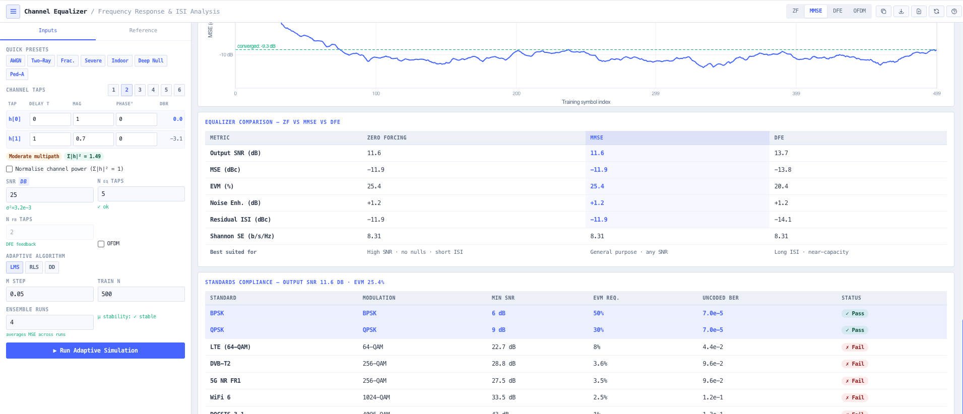
Output SNR and EVM checked against minimum receiver SNR thresholds for BPSK, QPSK, 64 QAM (LTE), 256 QAM (DVB T2 and 5G NR FR1), 1024 QAM (WiFi 6), and 4096 QAM (DOCSIS 3.1). Pass or fail status updates instantly as channel or equaliser parameters change, supporting rapid margin analysis during receiver design.
ZF versus MMSE versus DFE comparison table
Side by side comparison of output SNR, EVM, residual ISI, noise enhancement, and complexity for the three equaliser structures on the same channel. Useful for architecture trade off discussions, design decision records, and explaining the choice between ZF, MMSE, and DFE to non specialist stakeholders.
Browser only computation
Runs entirely in your browser. No channel models, equaliser configurations, or design data are submitted to a server. Useful for commercially confidential modem design work, defence and intelligence communications development, and environments where information security policy prohibits sending engineering data to third party services.
Inputs and outputs
What goes in, what comes out
Inputs 11
Up to six multipath taps with delay (fractional symbol periods), magnitude (dB or linear), and phase (degrees)
Operating SNR in dB
Equaliser type (Zero Forcing, MMSE, DFE, OFDM per subcarrier)
Number of equaliser taps for single carrier
OFDM mode toggle
Adaptive algorithm (LMS, RLS, decision directed)
LMS step size mu
RLS forgetting factor lambda
Number of training symbols
Optional channel preset (AWGN, two ray, indoor, severe, deep null, ITU Pedestrian A)
Target standard for compliance check (LTE, 5G NR, DVB T2, WiFi 6, DOCSIS 3.1)
Outputs 16
Equaliser tap weights for ZF, MMSE, and DFE
Channel frequency response H[k]
Equaliser frequency response W[k]
Combined channel and equaliser response C[k]
Group delay across the frequency band
Output SNR for each equaliser type
Mean squared error (MSE)
EVM in per cent and dBc
Noise enhancement in dB
Residual ISI in dB
Shannon spectral efficiency in b per s per Hz
Eye diagram before and after equalisation
ISI impulse response plot
Adaptive LMS, RLS, or DD convergence plot
Standards compliance verdict and margin
ZF versus MMSE versus DFE comparison table
Standards & methodology
3GPP TS 38.214. 5G NR receiver requirements
3GPP TS 36.213. LTE receiver requirements
IEEE 802.11ax. WiFi 6 PHY specification
ETSI EN 302 755. DVB T2 system specification
CableLabs DOCSIS 3.1 PHY specification
ITU R M.1225. Guidelines for the evaluation of radio transmission technologies (Pedestrian A reference channel)
Forney bound for Decision Feedback Equaliser SNR
Use cases
When to use this tool
01Computing ZF, MMSE, and DFE tap weights for a wideband multipath channel
02Evaluating EVM and output SNR against LTE, 5G NR, and WiFi 6 receiver requirements
03Analysing noise enhancement and spectral null sensitivity for ZF equalisers
04Choosing LMS step size and RLS forgetting factor for adaptive modem design
05Comparing equaliser structures to inform receiver architecture trade offs
06Teaching channel equalisation concepts with interactive frequency response plots
07Validating OFDM per subcarrier equalisation assumptions against single carrier alternatives
08Assessing ISI profile before and after equalisation using impulse response plots
09Evaluating DFE versus linear equaliser performance on severe multipath channels
10Producing teaching materials and reference visualisations for DSP courses
11Sanity checking vendor modem equaliser performance against the underlying channel
12Verifying that an adaptive equaliser converges fast enough for fast fading environments
What is channel equalisation and why do I need it?
Real RF channels are not flat. Multipath reflections produce frequency selective fading and inter symbol interference, where each transmitted symbol smears into its neighbours and the receiver cannot decide which symbol was sent. Equalisation is the process of estimating the channel and applying a compensating filter at the receiver before symbol decisions are made. Without equalisation, wideband digital communication over multipath channels falls apart at the higher modulation orders (256 QAM, 1024 QAM, 4096 QAM) where the symbol decision regions are smallest.
When should I use ZF, MMSE, or DFE?
Zero Forcing inverts the channel completely. It is ideal at very high SNR with no spectral nulls but suffers severe noise enhancement at frequencies where the channel response approaches zero. MMSE balances ISI cancellation and noise enhancement and is optimal across all SNR regimes. It is the standard choice for most modems. DFE adds a feedback filter that cancels post cursor ISI from past decisions, approaching the Shannon capacity bound on severe multipath channels at the cost of error propagation when wrong decisions feed back. The calculator computes all three simultaneously so the trade off is visible.
How is the channel modelled?
Up to six multipath taps with fractional delays handled via exact sinc interpolation in the frequency domain. Channel transfer function H[k] equals sum over n of h[n] times exp of (minus j 2 pi k tau[n] divided by N), evaluated across 256 frequency points. Each tap has independent delay (in fractional symbol periods), magnitude, and phase. Built in presets cover the common reference channels including the ITU Pedestrian A.
What is the difference between LMS, RLS, and decision directed?
LMS (Least Mean Squares) updates the equaliser tap weights with a small step toward the gradient of the error each symbol. Simple, low complexity, slow convergence. RLS (Recursive Least Squares) maintains an estimate of the inverse correlation matrix using a Kalman gain update. Faster convergence at O(N squared) complexity per symbol. DD (Decision Directed) uses the receiver decisions as the reference signal once initial convergence is achieved, useful for tracking slow channel variations after the training preamble ends.
How does OFDM equalisation differ from single carrier?
In OFDM the cyclic prefix removes ISI between OFDM symbols entirely, so the equaliser only needs to compensate per tone amplitude and phase distortion. This reduces equaliser complexity from O(K times N equaliser) for single carrier time domain equalisation to O(K) for OFDM per subcarrier equalisation. The MMSE per subcarrier weight is W[k] equals H conjugate of [k] divided by (magnitude H squared plus sigma squared). LTE, 5G NR, and WiFi all use this approach because of the complexity advantage on wideband channels.
How is DFE SNR computed?
The Forney bound. SNR DFE equals exp of ((1 over N) times sum over k of ln of (1 plus SNR times magnitude H squared)) minus 1. This is the theoretical SNR achievable by an ideal infinite length DFE assuming no decision errors. Real DFE implementations approach this bound on severe multipath channels but suffer error propagation when wrong decisions feed back, so the practical performance sits below the bound by a small margin.
Can I check standards compliance directly?
Yes. Output SNR and EVM are checked against minimum receiver SNR thresholds for BPSK, QPSK, 64 QAM (LTE), 256 QAM (DVB T2 and 5G NR FR1), 1024 QAM (WiFi 6), and 4096 QAM (DOCSIS 3.1). Pass or fail status updates as channel or equaliser parameters change. Useful for confirming whether a candidate receiver design will achieve the target modulation order on a given channel.
Does any data leave my browser?
No. The calculator runs entirely in your browser. No channel models, equaliser configurations, or design data are submitted to a server. Useful for commercially confidential modem design work, defence and intelligence communications development, and environments where information security policy prohibits sending engineering data to third party services.