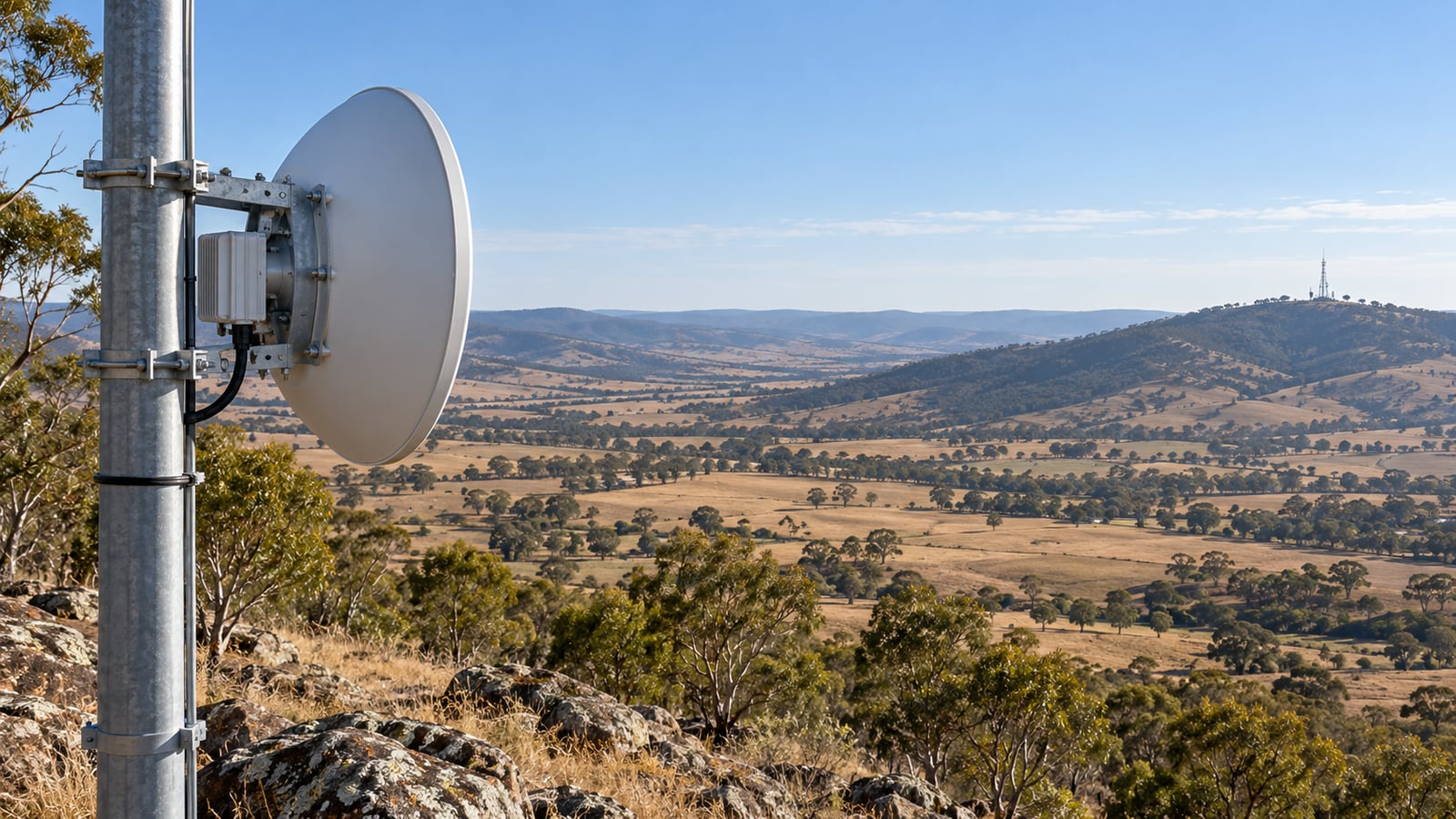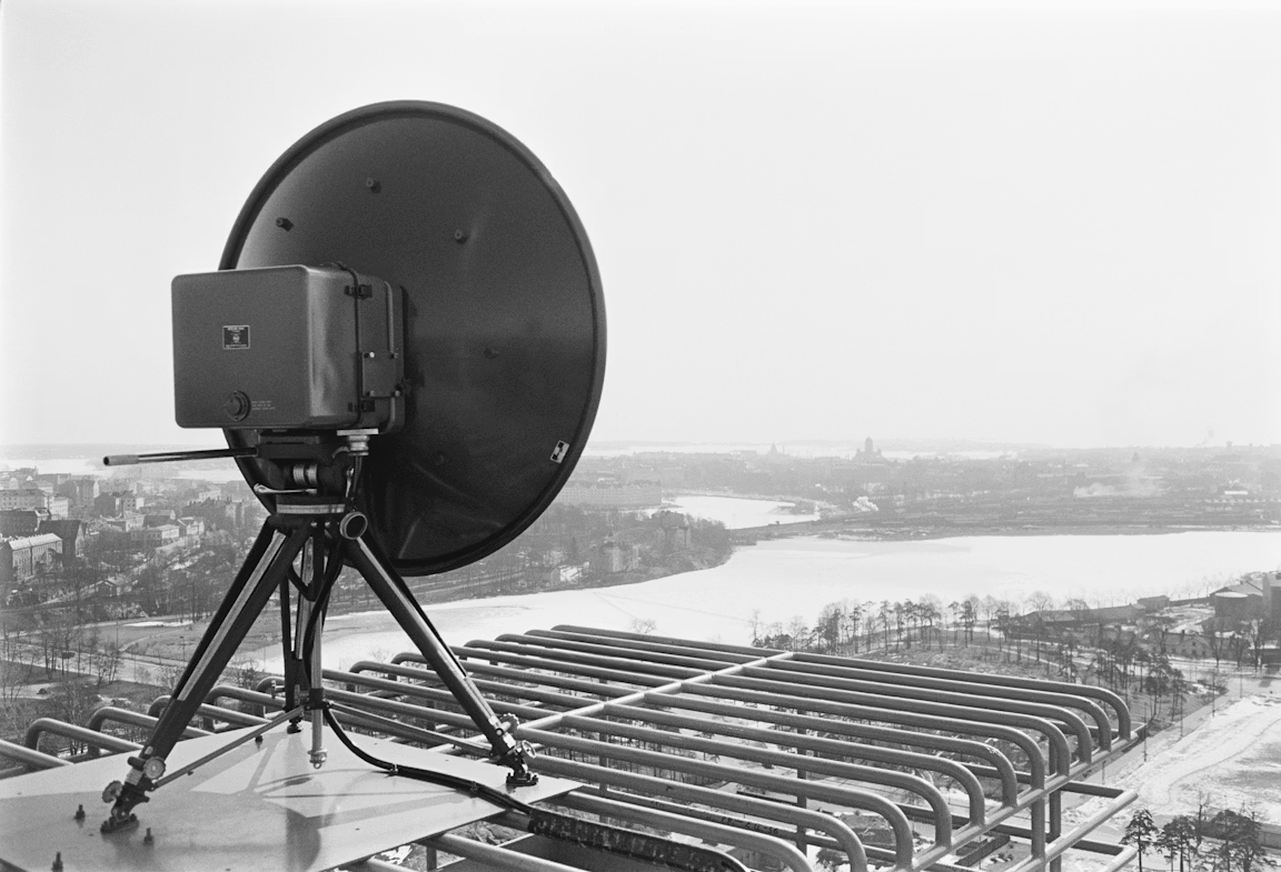
A point-to-point link joins two sites with a pair of radios and directional antennas. On paper it is the simplest network there is. In practice the design has to answer four questions before anything is ordered: can the two antennas see each other with enough room around the beam, which band will survive the local rain, which radio and dishes give the speed you need, and for how much of the year.
This guide answers those questions on a real path, a 25.7 km hop from a hilltop near Orange in New South Wales down to a site in the valley to the south-east. Every figure and screenshot comes from the noIM₃ Link Planner, so you can follow along and change any input to see what moves.
The first attempt fails, which is the useful part. It shows why a link that clears the terrain can still be the wrong design.
The Short Answer
To design a point-to-point link, work in this order:
- Set the target: the capacity the service needs and the availability it must hold.
- Place both sites and draw the link between them.
- Read the path profile and check Fresnel zone clearance against ITU-R P.530-19.
- Choose a band that the local rain allows at your path length.
- Choose the radio and antennas from real equipment data.
- Recheck clearance and set the antenna heights with some margin.
- Check the link budget in both directions.
- Confirm availability mode by mode against the target.
- Plan the frequency and the licence.
- Export the design for the customer and the installers.
Here is how the example link changed between the first attempt and the final design.
| First attempt | Final design | |
|---|---|---|
| Band | 18 GHz | 11 GHz |
| Radio and antennas | Generic defaults | Cambium PTP 820C, 1.2 m dishes |
| Antenna heights (hilltop, plant) | 30 m, 10 m | 30 m, 15 m |
| Clearance margin at the critical point | 1.3 m | 5.7 m |
| Rain loss exceeded 0.01 % of the year | 36.1 dB | 14.3 dB |
| Best availability of any mode | 99.985 % | 99.9997 % |
| Capacity committed at 99.99 % | None | 493 Mbps |
| Target: 200 Mbps at 99.99 % | Fails | Passes |
The Example Path
The link runs from a hilltop site at 1386 m above sea level to a site we call the plant, 25.7 km away and about 900 m above sea level. The coordinates are -33.3443, 148.9817 for the hilltop and -33.5469, 149.1157 for the plant, so you can build the same path yourself.
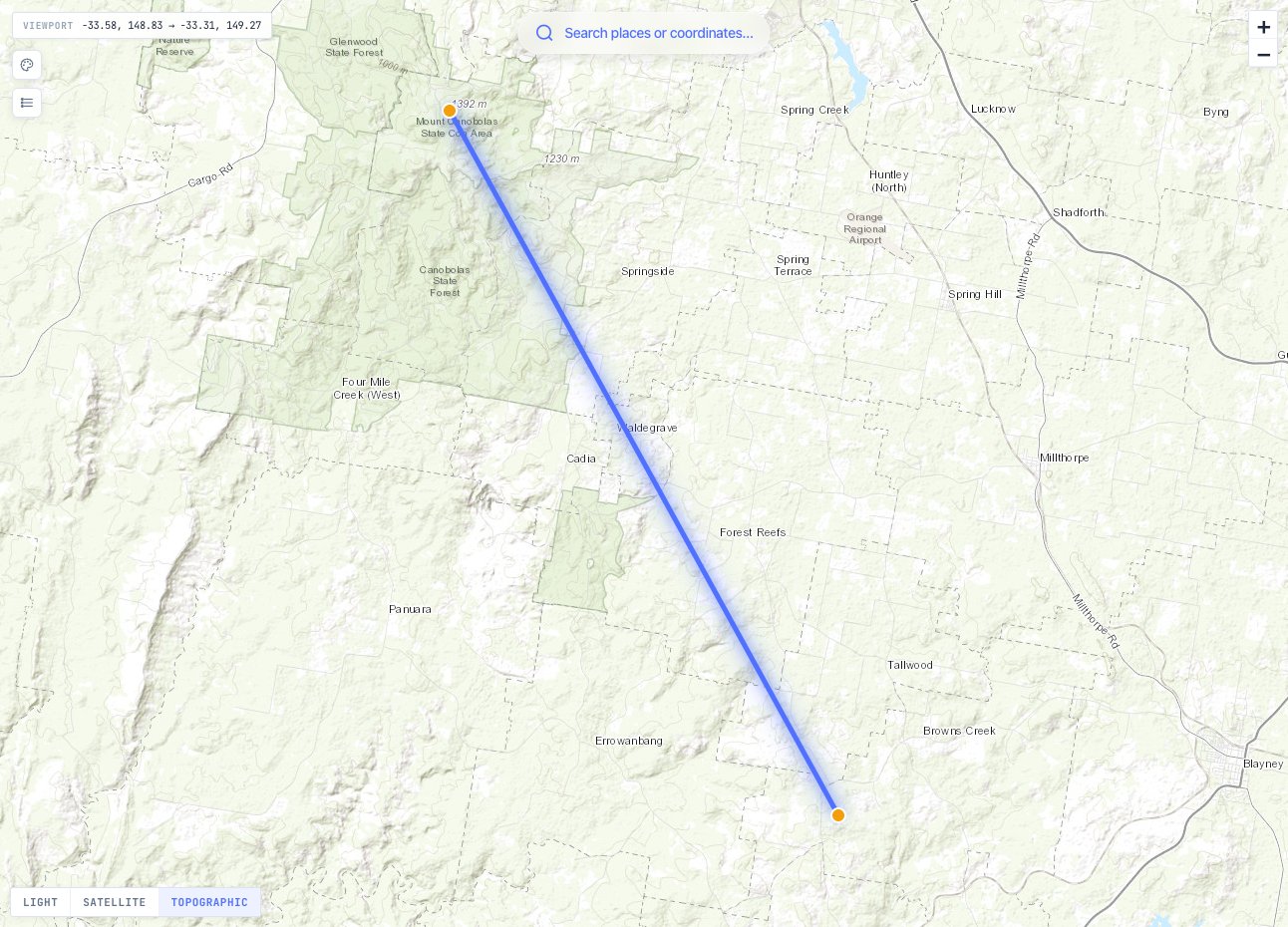
A hilltop to valley path is a common shape for a real link. One end is high and the other is not, so most of the profile is easy and the trouble, if there is any, sits near the low end.
Step 1: Set the Design Target
Start with what the service needs, not with the fastest radio you can buy. For this example the target is 200 Mbps in each direction at 99.99 % availability.
Availability of 99.99 % allows about 53 minutes a year below the target speed. The planner applies the target to each direction separately and reports the simultaneous two-way figure on its own, because rain can hit the two directions at slightly different levels and a single headline would hide that.
The Link Planner keeps the target in the link’s Config tab. Every result from then on is judged against it, so the tool tells you whether the link passes rather than leaving you to read it off a table.
Step 2: Place the Sites and Draw the Link
Place a network site at each end, either by clicking the map, searching for coordinates or importing a CSV of sites. Each site takes its ground height from the terrain data. Give each site the tallest antenna height its structure allows. The planner treats that as the ceiling when it looks for a height that clears the path.
Then draw the link from one site to the other. The planner samples the terrain along the path, applies the earth’s curvature and runs the full link calculation straight away. If the path cannot clear the terrain even at the tallest structure heights, the link is still kept but marked as not viable, with the distance and depth of the obstruction, so you can fix it in place.
New links start at 18 GHz with generic radio and antenna values (23 dBm transmit power, 38.4 dBi antennas and a 6 dB noise figure). Those defaults are labelled as placeholders. They are there so you can compare bands before choosing equipment, not to stand in for it.
Step 3: Read the Path Profile
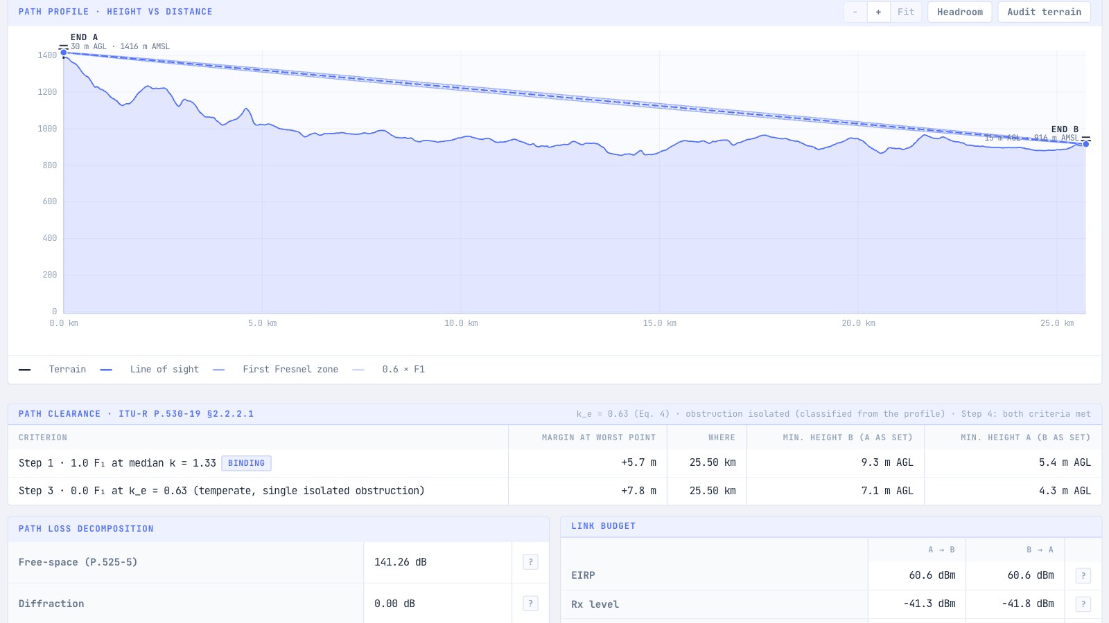
The path profile is the heart of the design. It shows the terrain, the line of sight between the antennas and the first Fresnel zone around it.
The first Fresnel zone is the football-shaped region around the direct path where most of the received energy travels. Terrain that intrudes into it adds loss even when the antennas can see each other. Its radius is largest at mid-path and grows as the frequency falls. On this path at 18 GHz it is about 10.3 m at the midpoint.
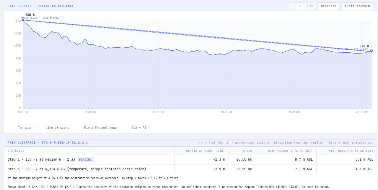
Below the chart, the planner checks clearance with the procedure in ITU-R P.530-19 §2.2.2.1, not a single rule of thumb. There are two criteria, and the antennas must satisfy both:
- Step 1: clear 1.0 of the first Fresnel zone radius (1.0 F1) under median refraction, an effective earth radius factor of k = 1.33.
- Step 3: clear a smaller fraction of F1 under the worst refraction expected for 0.1 % of the worst month, a factor called ke. In a temperate climate the fraction is 0.0 F1 for a single isolated obstruction and 0.3 F1 for an obstruction that runs along part of the path.
For this path ke is 0.63, and the planner classifies the obstruction from the profile itself. Step 1 binds. For each criterion the table also gives the minimum antenna height at each end, with the other end as set, which is the number you actually need when talking to a tower crew.
Notice where the critical point is: 25.50 km along a 25.69 km path, 190 m in front of the plant. That is typical of a hilltop to valley path. The ground near the low end is what limits the design, and it is also where trees, sheds and fences the elevation data does not hold are most likely to be. If you know about them, draw them on the map as clutter zones and they become part of the profile.
The 0.6 F1 line on the chart is the familiar 60 % rule. It is shown for reference only; the pass or fail comes from the P.530 procedure. Our guide to Fresnel zones and the 80 percent rule explains where the rule of thumb came from.
Step 4: Choose the Band
The path clears at 18 GHz, but clearance is only half the story. The other half is rain.
Rain attenuates microwave signals, and the loss climbs steeply with frequency. ITU-R P.837-8 puts the rain rate exceeded for 0.01 % of the year at this location at 35.7 mm/h. Over 25.7 km at 18 GHz, ITU-R P.530-19 turns that into 36.1 dB of rain loss exceeded for 0.01 % of the year.
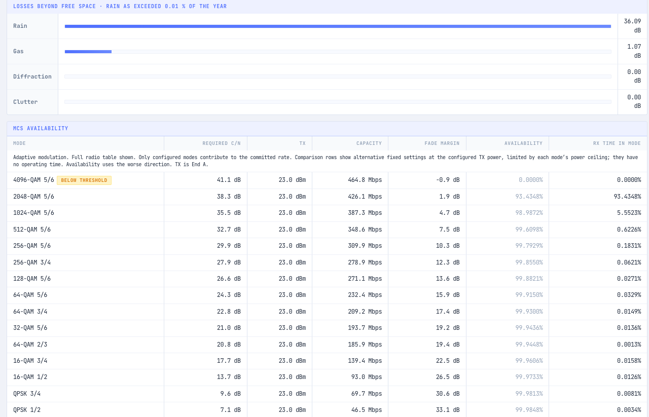
The table lists every modulation mode the radio could use, from the fastest to the most robust, with its fade margin and predicted availability. With the generic defaults, the mode that would carry 200 Mbps (64-QAM 3/4 at 209 Mbps) holds 99.93 %. Even QPSK 1/2 at 46.5 Mbps only reaches 99.985 %. The headline reads 0.0 Mbps committed at 99.99 %, and the Config tab marks the requirement as failed.
You could chase this with bigger dishes and more power, but you would be fighting the band. Dropping to 11 GHz cuts the rain loss on the same path to 14.3 dB, because the specific attenuation falls to 1.04 dB/km. Free space loss also drops by 4.5 dB. In the planner this is one change on the Config tab: the band list offers the ITU-R F-series channel arrangements, and choosing 11 GHz sets a 56 MHz channel pair at 10737 MHz and 11267 MHz.
As a rule, the longer the path and the wetter the climate, the lower the band you need. Our guide to rain fade and link availability covers the method in more depth.
Step 5: Choose the Radio and Antennas
Once the band is settled, replace the generic values with real equipment. The Select radio window lists the radios in the catalogue that cover the link frequency. A radio badged with a datasheet carries its receiver thresholds for each mode, which is what lets the planner work out capacity and availability for that radio rather than a generic one.
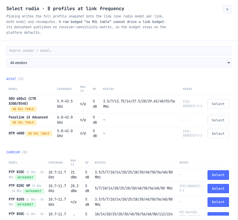
For this example we chose the Cambium PTP 820C at 11 GHz, which has a datasheet threshold table in the catalogue and a maximum transmit power of 21 dBm. The choice is an example, not a recommendation.
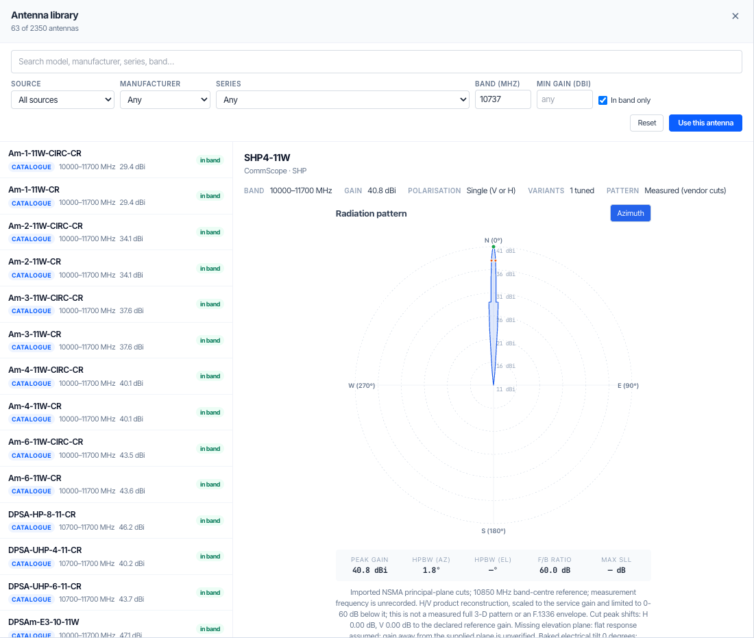
Antennas come from the antenna library, filtered to the link frequency. Selecting one shows its gain, beamwidth and radiation pattern. We used a 1.2 m CommScope SHP4-11W at each end, with 40.8 dBi of gain and a 1.6° 3 dB beamwidth.
With both ends set, the Config tab shows the whole design on one page: the target and whether it passes, the band and channel, the antennas and the radio.
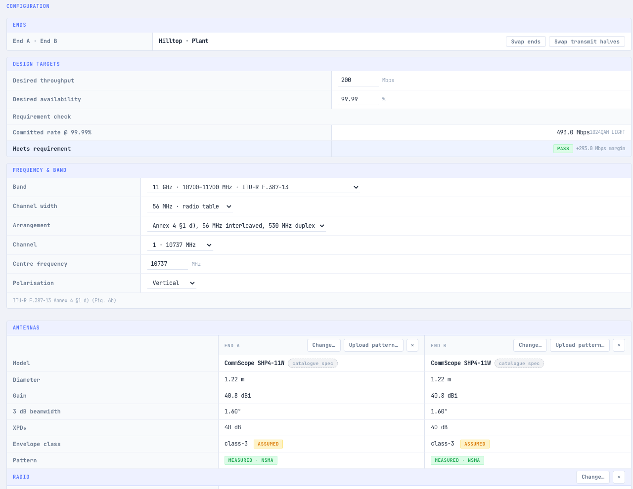
Look at the badges. The antenna envelope class is marked as assumed, and so is the receiver noise figure of 5 dB. Until inputs like these are confirmed, the link carries a Provisional inputs flag in the project tree. That is worth knowing before a design goes to a customer.
Step 6: Recheck Clearance and Set the Antenna Heights
Changing the band changes the clearance. A lower frequency has a wider Fresnel zone: at 11 GHz the mid-path radius on this link is about 13.4 m, against 10.3 m at 18 GHz. At the critical point near the plant the margin fell from 1.3 m to 0.7 m.
A 0.7 m margin passes, but it leaves nothing for a tree or a shed the elevation data does not show. Raising the plant antenna from 10 m to 15 m lifts the margin to 5.7 m under Step 1 and 7.8 m under Step 3.
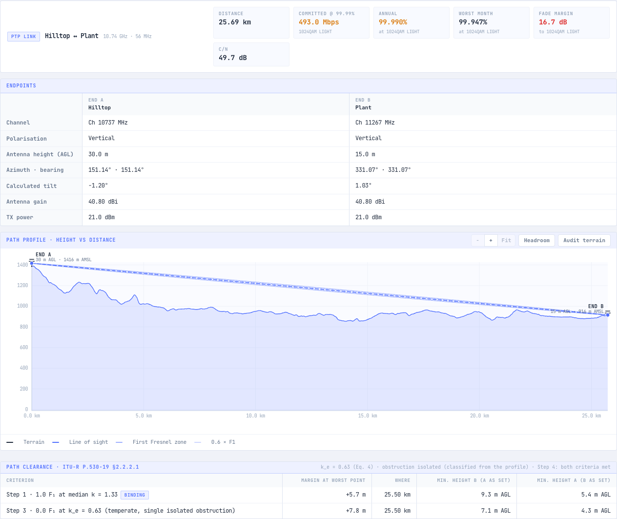
How much margin to add is a judgement call. The clearance check adds no allowance for errors in the elevation data, because no vertical accuracy is published for the global terrain source it uses. A site visit to the low end, or survey terrain loaded into the project, is the way to firm it up.
Step 7: Check the Link Budget
The link budget adds up gains and losses from one transmitter to the other receiver. The planner shows it in both directions, because the two directions use different frequencies.
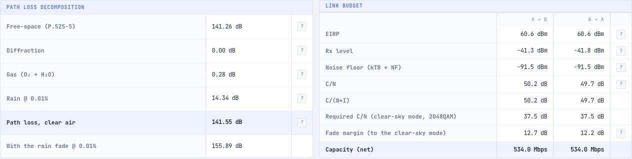
You can check the arithmetic for the hilltop to plant direction by hand:
- EIRP: 21 dBm transmit power + 40.8 dBi antenna gain - 1.2 dB feeder loss = 60.6 dBm.
- Free space loss: 92.45 + 20 log(10.737 GHz) + 20 log(25.69 km) = 141.26 dB, from ITU-R P.525.
- Clear-air path loss: 141.26 dB plus 0.28 dB of atmospheric gas from ITU-R P.676-13 = 141.55 dB.
- Receive level: 60.6 dBm - 141.55 dB + 40.8 dBi - 1.2 dB = -41.3 dBm.
- Noise floor: -174 dBm/Hz + 10 log(56 MHz) + 5 dB noise figure = -91.5 dBm.
- C/N: -41.3 dBm - (-91.5 dBm) = 50.2 dB.
- Fade margin at 2048-QAM: 50.2 dB - 37.5 dB required = 12.7 dB.
In clear weather the link runs at 2048-QAM and 534 Mbps. The 12.7 dB margin is less than the 14.3 dB rain loss, so in the heaviest rain the radio has to step down. That is exactly what adaptive modulation is for, and it is why the next step looks at every mode, not just the fastest one. Our guide to calculating an RF link budget explains each term.
Step 8: Confirm Availability Mode by Mode
A link with adaptive modulation does not simply work or fail. It runs faster in clear air and slower in rain, so availability has to be read per mode.
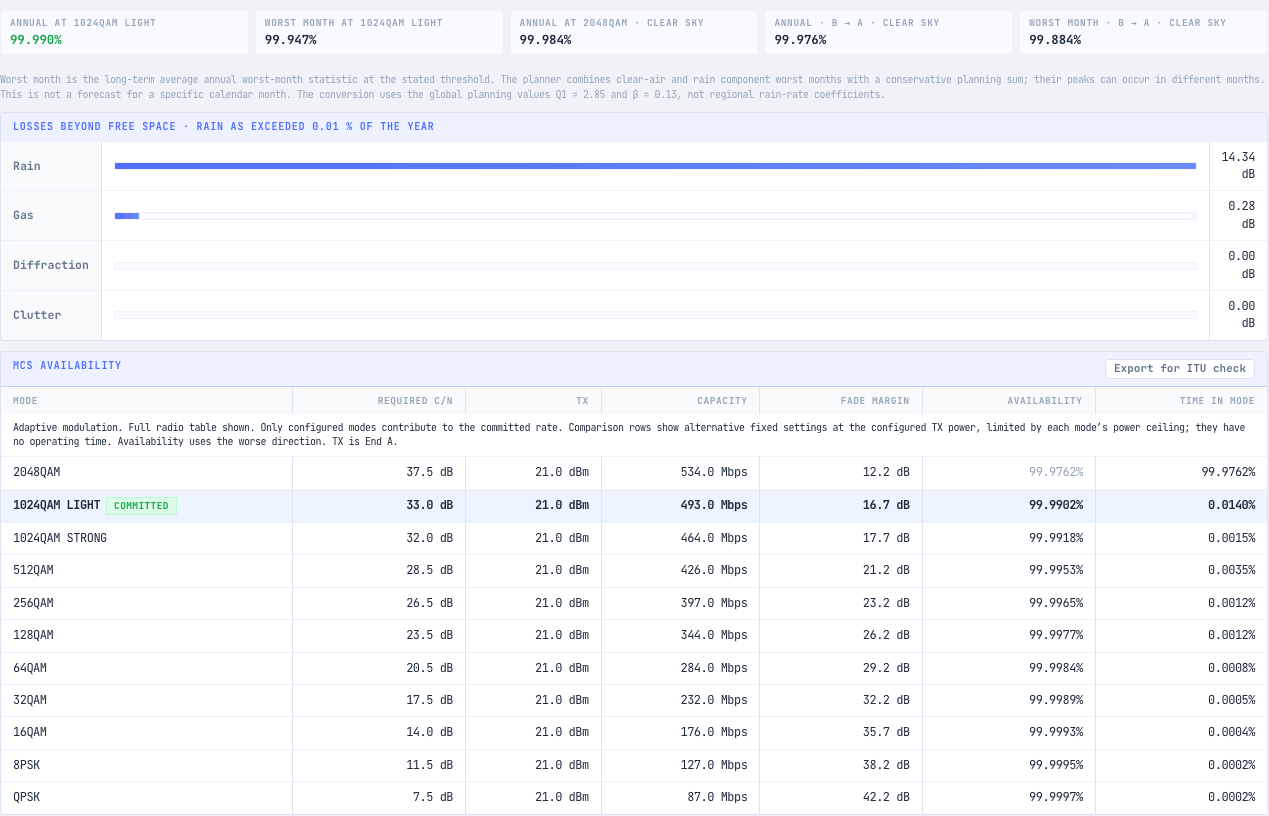
The committed mode is the radio’s 1024-QAM light mode, at 493 Mbps and 99.990 % availability in the worse direction, with a 16.7 dB fade margin. In practice that means:
- The link is predicted to run at 493 Mbps or better for all but about 52 minutes a year.
- 200 Mbps, the actual target, is carried by every mode down to 32-QAM at 232 Mbps, which holds 99.9989 %.
- The link is predicted to lose connection entirely, below QPSK, for under 2 minutes a year.
The worst month matters too. The planner predicts 99.947 % for the worst month of an average year, because outage bunches into the months with the heaviest rain and the most multipath fading. That is worth telling whoever owns the service level.
The tab also checks the link against the ITU-R F.1703 availability objectives and the ITU-R F.1668 error performance objectives, and both pass. Each result says which direction binds and which inputs were assumed.
Step 9: Plan the Frequency and Licence
Most bands used for fixed links, including 11 GHz, are licensed. Each link needs a licence from the national regulator and coordination with the links already on air nearby. Some bands, such as 5.725 to 5.850 GHz in Australia, can be used under a class licence instead, with lower power limits and no protection from interference.
This example has no regulator set, so it uses the ITU-R channel arrangements. An Australian project can be switched to ACMA in Project settings. The planner then uses the RALI FX 3 channel plans, adds a Compliance tab and screens the link against registered services nearby. That screen helps prepare an application; it is not the coordination itself. Our guide on how to get a radio licence in Australia explains the process.
Step 10: Export the Design
The Report tab turns the design into documents you can hand on.
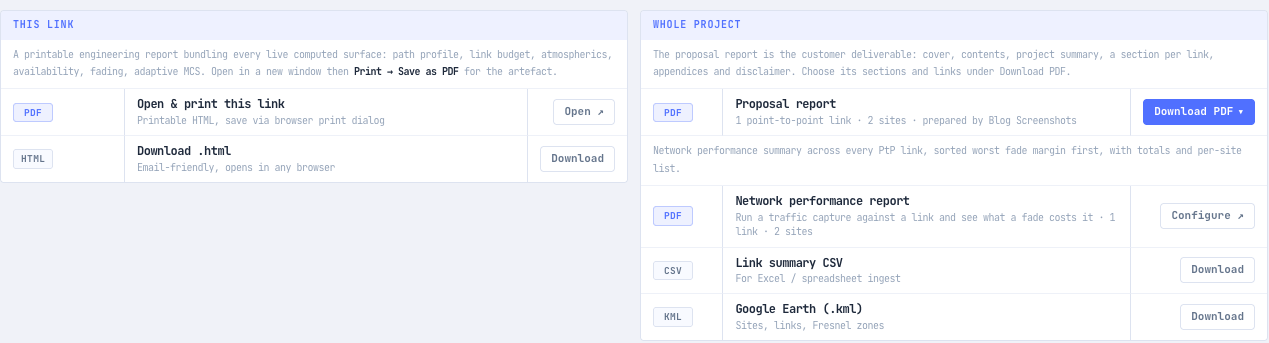
The engineering report bundles the profile, budget, atmospherics, availability and fading for one link, with the Recommendation and edition behind each figure. The proposal report is the customer-facing PDF for the whole project. The CSV and KML exports take the network into a spreadsheet or Google Earth.
Common Mistakes When Designing a Point-to-Point Link
- Stopping at line of sight. Being able to see the far end does not mean the Fresnel zone is clear, and a clear Fresnel zone does not mean the link holds its target in rain.
- Picking the band before the path. A band that works at 5 km can be hopeless at 25 km. The 18 GHz attempt here cleared the terrain and still could not hold 99.99 %.
- Designing to the clear-sky speed. The headline speed on a datasheet is the fastest mode. The speed you can promise is the one the link holds at the target availability.
- Trusting the elevation data at the low end. The critical point on this path is 190 m from the plant, where trees and buildings matter most and the terrain data says least.
- Leaving placeholders in the design. Generic transmit power, gain and noise figure are fine for comparing options and wrong for a design that goes to a customer.
Frequently Asked Questions
What do you need to design a point-to-point link?
You need the coordinates and ground heights of both sites, the tallest antenna height each structure allows, the capacity and availability the service needs, and data for the radio and antennas. Terrain along the path, rain statistics for the location and the regulator’s channel plans come from the planning tool.
How much Fresnel zone clearance does a point-to-point link need?
ITU-R P.530-19 §2.2.2.1 sets two criteria, and both must be met. The antennas must clear 1.0 of the first Fresnel zone under median refraction (k = 1.33), and a smaller fraction, from 0.0 to 0.3 F1 in temperate climates, under the worst refraction expected for 0.1 % of the worst month. The common 60 % rule is a simplification of this.
Which frequency band should I use for a point-to-point link?
Use the highest band that still holds your availability target at the path length, because higher bands usually offer wider channels and smaller antennas. Rain sets the limit. On this 25.7 km path, 18 GHz lost 36.1 dB to rain at 0.01 % of the year and failed, while 11 GHz lost 14.3 dB and passed.
What is a good fade margin for a point-to-point link?
There is no single good figure. The fade margin a mode needs is the one that keeps it above its threshold through multipath fading and rain for the target percentage of the year. In this example 1024-QAM light holds 99.99 % with a 16.7 dB margin, while 2048-QAM with 12.7 dB does not.
Why does a point-to-point link slow down in heavy rain?
Radios with adaptive modulation step down to more robust, slower modes when the received signal fades. The link stays up at a lower speed instead of dropping out. A good design checks that the slower mode it falls back to still carries the traffic the service needs.
How far can a point-to-point link go?
It depends on the antenna heights, the terrain, the band and the local rain rate. Line of sight over smooth earth is limited by the radio horizon, but in practice clearance and rain usually set the limit first. Our guide to radio line of sight and the radio horizon shows how to work out the geometric limit.
Design Your Own Link
The Link Planner runs every step in this guide on your own sites: the path profile, the P.530-19 clearance check, the band, radio and antenna choice, both link budgets and availability for every mode. It is part of noIM₃ Pro, and new accounts start with a free 14-day Pro trial.
For quick single checks, the free Fresnel Zone Calculator, Link Budget Calculator and Rain Fade Calculator cover one part of the design each. For more on the theory behind each step, read our step-by-step guide to microwave link planning.
Notes on Sources
Every figure in the worked example comes from one run of the noIM₃ Link Planner (build 1.7.1) on 9 November 2026. Terrain was sampled from Mapbox Terrain-RGB elevation data, which has no published vertical accuracy. Radio and antenna values are as held in the noIM₃ catalogue from the manufacturers’ published data; the receiver noise figure and antenna envelope class are assumptions and are labelled as such in the tool. The example is a planning prediction, not a site survey, and it does not describe any existing installation. The midpoint Fresnel radii and the hand check of the link budget are our own arithmetic.
- ITU-R P.530-19, Propagation data and prediction methods required for the design of terrestrial line-of-sight systems: §2.2.2.1 for the clearance procedure, and the rain, multipath and availability methods behind the results.
- ITU-R P.837-8, Characteristics of precipitation for propagation modelling, for the 35.7 mm/h rain rate; ITU-R P.838-3 for rain specific attenuation; ITU-R P.839-4 for rain height.
- ITU-R P.525, Calculation of free-space attenuation, and ITU-R P.676-13, Attenuation by atmospheric gases.
- ITU-R F.387-13 and ITU-R F.595-11, the radio-frequency channel arrangements for the 11 GHz and 18 GHz bands.
- ITU-R F.1703 and ITU-R F.1668, for the availability and error performance objectives.
- ACMA RALI FX 3, for Australian fixed link channel plans and coordination.