Why this refresher matters
Most propagation related link failures in the field are not exotic. They tend to cluster around the same four issues: underestimated path loss, a clipped Fresnel zone, ground reflection cancellation, or a margin that looked fine on paper and evaporated in rain. These four account for a large share of propagation related failures, though interference, hardware faults, and installation errors are also common contributors in the field.
Modern planning tools do the heavy lifting, but engineers who understand why the numbers come out the way they do make better decisions on site, where the simulator isn’t open, the mast isn’t where the KMZ said it would be, and a call has to be made in the next ten minutes.
This post is a working refresher on four fundamentals: free space path loss, log distance path loss, Fresnel zones, and two ray ground reflection.
Loading the Fresnel Zone Calculator…
1. Free space path loss: the baseline reference
Free space path loss (FSPL) is the loss a signal experiences travelling through a vacuum with no obstructions, no reflections, and no absorption. It is the baseline reference against which every real link is compared, and under most conditions a real link will be worse.
The standard form in decibels:
FSPL (dB) = 20·log10(d) + 20·log10(f) + 32.44
…with d in kilometres and f in MHz.
Two things about FSPL that field engineers sometimes forget:
- Doubling the distance adds 6 dB, not 3 and not 10, but a clean 6.
- Doubling the frequency also adds 6 dB. A 4.8 GHz link has 6 dB more free space loss than a 2.4 GHz link over the same distance, before you consider anything else, and the common 2.4 versus 5 GHz comparison is close to but not exactly a doubling, giving roughly 6.4 dB.
FSPL is the anchor for every link budget. Real world measurements can occasionally appear better than FSPL due to antenna gain, ducting, or waveguiding effects, but a propagation model should not predict less propagation loss than free space. If yours does, the model is wrong.
Run the numbers: FSPL Calculator →
2. Log distance path loss: what actually happens
Real environments are not vacuums. Buildings, foliage, terrain, and atmospheric effects all add loss above the free space floor. The log distance model captures this with two fitted parameters, a path loss exponent n and a shadowing standard deviation σ:
PL(d) = PL(d0) + 10·n·log10(d / d0) + Xσ
Where:
PL(d0)is the loss at a reference distance (often 1 m or 100 m)nis the path loss exponent, the environmental multiplierXσis a log normal shadowing term for fading variability
Typical values for n:
| Environment | Path loss exponent (n) |
|---|---|
| Free space | 2.0 |
| Urban area (line of sight) | 2.7 to 3.5 |
| Urban area (obstructed) | 3.0 to 5.0 |
| Indoor (line of sight) | ~1.6 to 2.0 (lower values typically in corridor like environments due to waveguiding) |
| Indoor (obstructed) | 4.0 to 6.0 |
The practical takeaway: in environments with path loss exponents of 3 to 4, doubling distance can add 9 to 12 dB or more rather than the 6 dB predicted by free space. Link budgets built on FSPL alone will over promise by a wide margin in anything but the most open terrain.
3. Fresnel zones and the 80% rule
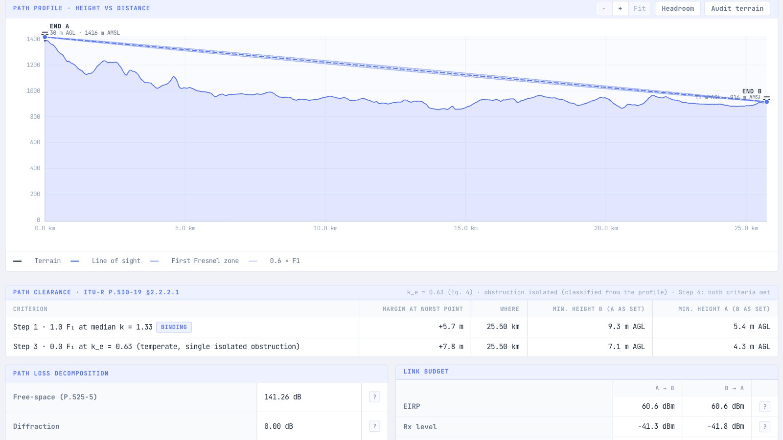
Line of sight on its own is not enough, because RF energy does not travel as a pencil beam. It travels as a family of ellipsoidal volumes called Fresnel zones. The first Fresnel zone contains the majority of the energy contributing to the received signal, and obstructions inside it cause significant additional loss even when there is nothing on the direct optical line.
The radius of the first Fresnel zone at the midpoint of a link:
r = 8.656 · √(d / f)
…with r in metres, d in kilometres (total link length), and f in GHz.
The rule every field engineer should know:
Keep at least 60% of the first Fresnel zone clear of obstructions. Planning to 80% clearance gives a margin that tolerates tree growth, vehicle movement, and survey error.
A quick example: a 10 km link at 5 GHz has a first Fresnel radius at midpoint of:
r = 8.656 · √(10 / 5) = 12.2 m
That is a 12 metre radius ellipsoid in the middle of the path. A ridge, treeline, or building 8 metres below the optical line will clip the zone and introduce additional loss, often several dB depending on the degree of obstruction, even though the link “has line of sight”.
At higher frequencies the zone shrinks, which means less physical clearance is required for the same percentage of Fresnel obstruction. That sounds helpful, but higher frequencies also suffer greater diffraction and penetration losses and higher FSPL overall, so the net effect on link performance depends on terrain, foliage, and building materials along the path.
Visualise the ellipsoid for your path: Fresnel Zone Calculator →
4. Two ray ground reflection: the distance everyone gets wrong
In ideal conditions over a smooth, reflective surface (water, paddock, tarmac, salt lake), a receiver sees two signals: the direct ray and the ground reflected ray. Depending on geometry, they add constructively or destructively.
Beyond a critical distance, the breakpoint, the two rays settle into predominantly destructive interference, and received power approaches a 1/d⁴ decay in the ideal two ray region rather than the 1/d² decay of free space. In real environments, surface roughness, scattering, and multipath from nearby objects often soften this transition.
The breakpoint distance:
d_break = (4 · h_t · h_r) / λ
Where h_t and h_r are the transmit and receive antenna heights, and λ is the wavelength.
At 2.4 GHz with two 10 m antennas, assuming free space wavelength and a flat, specular reflecting surface, the breakpoint is roughly 3.2 km. Beyond that, path loss grows at approximately 40 dB per decade of distance rather than 20 dB per decade. That is the reason links across water, salt pans, and open coastal ground frequently underperform their free space predictions.
Mitigations:
- Raise antenna heights (the breakpoint scales with the product
h_t · h_r, so raising both antennas has the largest effect) - Use higher frequencies, which extend the breakpoint, noting this also increases free space and atmospheric losses
- Tilt antennas to reduce ground illumination
- Where practical, choose terrain with scattering rather than specular reflection
Putting the four together
A useful field sanity check before committing to a link:
- Calculate FSPL for your distance and frequency. This is your baseline reference.
- Add environmental loss using a log distance exponent appropriate for the terrain.
- Verify 60% first Fresnel zone clearance at the worst midpoint.
- Check whether the path crosses a large reflective surface and estimate the breakpoint.
- Check for interference sources and the available noise floor, particularly in unlicensed bands.
If any of these checks fails, the link is unlikely to close reliably, or will close with insufficient margin to survive weather, seasonal foliage, or local interference events.
How noIM₃ fits in
The noIM₃ platform includes dedicated calculators for each of these fundamentals. FSPL, log distance path loss, Fresnel zone, and two ray ground reflection, alongside a full point-to-point Link Planner that combines them with antenna, cable, ITU-R rain/multipath, and fade margin inputs. The aim is not to replace engineering judgement but to make the numbers fast enough that you can run three or four scenarios before you commit to a mast height or a frequency choice.
For regulatory work such as frequency coordination, interference prediction, and ACMA compliance, the same propagation fundamentals feed directly into the frequency planning and validation tools.
Key takeaway
Between them, these calculations cover many of the most common propagation related mistakes made in the field. None of them requires a supercomputer. All of them reward being internalised until they are instinctive.
A good field engineer does not need to remember every formula, but they should know, within a few dB, what the answer is going to be before the tool gives it to them. That is the difference between using a calculator and engineering a link.