The Short Answer
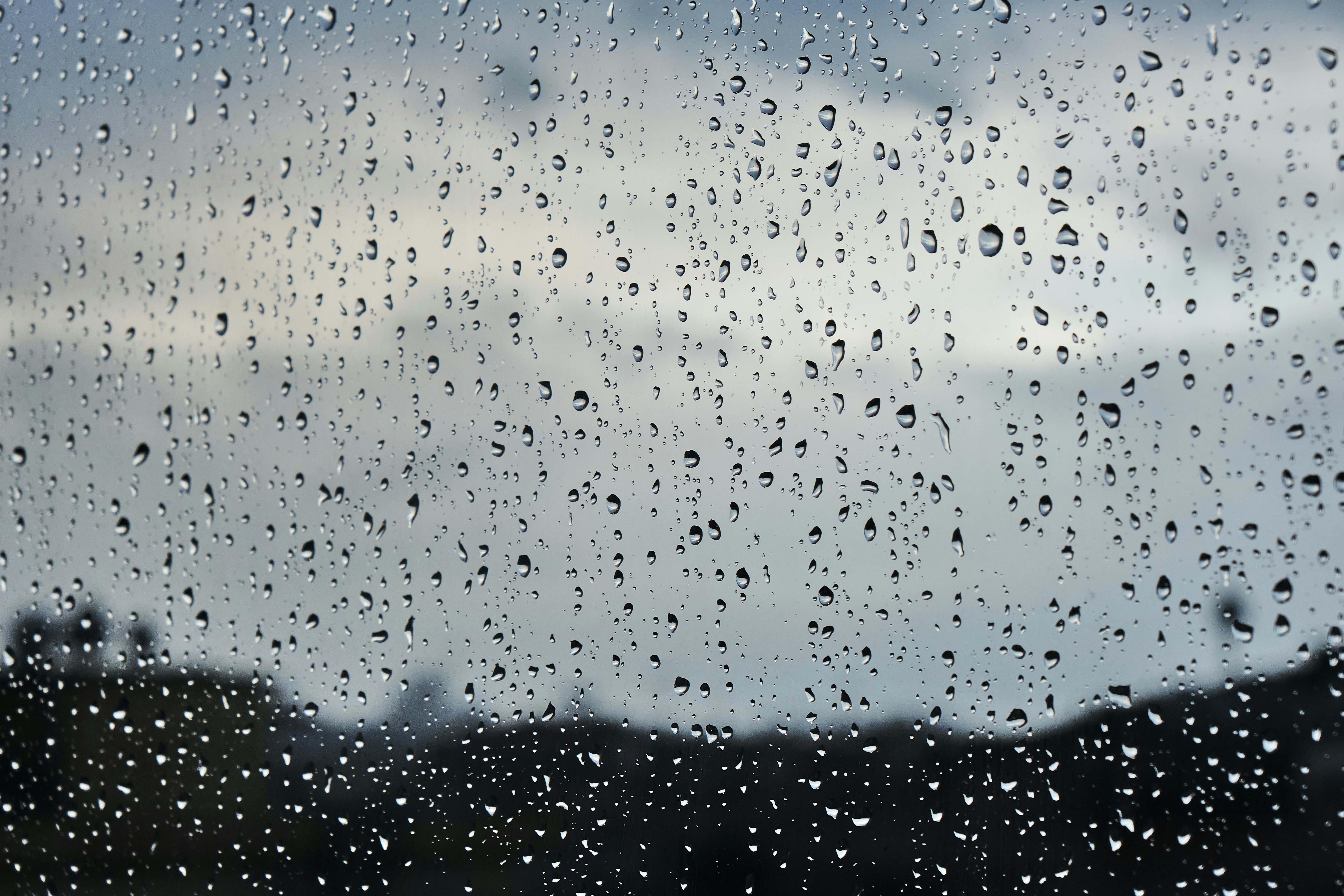
Rain fade is the additional loss a radio signal suffers when rain falls along the path, on top of the free space path loss that is always present. Raindrops absorb and scatter energy, and because a drop is roughly the same size as the wavelength at microwave frequencies, the effect grows quickly with frequency. Below about 10 GHz it is usually negligible for terrestrial microwave links. Above 10 GHz it becomes significant, and above 15 GHz it is normally the dominant fading mechanism and the factor that sets the design.
The loss is worked out in two steps. First you find the specific attenuation γ, in decibels per kilometre, from the rain rate and a pair of frequency dependent coefficients:
γ = k · R^α
Here γ is the specific attenuation in decibels per kilometre, R is the rain rate in millimetres per hour, and k and α are the coefficients from ITU-R P.838. Then you multiply that by an effective path length, which is shorter than the real hop because heavy rain falls in cells rather than evenly along the whole path. The result is the rain attenuation to include in the link budget at your chosen availability. A link that ignores rain fade will look healthy on a clear day and drop out in the first serious storm.
The Physics: Specific Attenuation and ITU-R P.838
Rain fade starts with specific attenuation, the loss per kilometre through a uniform curtain of rain of a given intensity. ITU-R Recommendation P.838 gives it as a simple power law of the rain rate:
γ = k · R^α
The coefficients k and α depend on frequency, on polarisation, and to a small degree on the drop temperature. Both rise in a way that makes higher frequencies far more vulnerable. At 20 GHz, horizontal polarisation, the P.838 tables give coefficients of about k ≈ 0.09 and α ≈ 1.06. At 6 GHz the same coefficients are tiny, which is exactly why long haul microwave and utility links have historically favoured the lower bands.
Polarisation matters more than most people expect. Raindrops are not spheres. As they fall they flatten into oblate shapes, wider than they are tall, so a horizontally polarised wave presents its electric field along the wider dimension and is attenuated more than a vertically polarised wave. For that reason vertical polarisation is the more rain robust choice on a marginal high frequency hop, and choosing it can claw back a useful decibel or two for nothing.
From a Rain Cell to a Real Hop
If rain fell evenly along the whole path, the total fade would simply be the specific attenuation times the path length. It does not. Intense rain falls in compact cells that rarely cover an entire long hop at once, so the loss grows more slowly than the raw length would suggest. ITU-R P.530 accounts for this with an effective path length that is shorter than the physical distance.
The classic form multiplies the real distance d by a distance factor r:
r = 1 / (1 + d / d₀), with d₀ = 35 · e^(−0.015 · R₀.₀₁)
Here R₀.₀₁ is the rain rate exceeded for 0.01 per cent of an average year, the standard reference rain rate. The effective length is then d_eff = d · r, and the fade exceeded for 0.01 per cent of the year is:
A₀.₀₁ (dB) = γ · d_eff
The current edition of P.530 uses a more detailed effective path expression that also depends on frequency and the path angle, and the rain fade calculator implements the recommended model in full. The simple form above is enough to build the intuition and to sanity check any tool: the effective length always sits below the physical length, and the gap widens as the rain rate climbs and the cell shrinks relative to the hop.
A Worked Example: 20 GHz Over 8 km
Take an 18 to 23 GHz backhaul hop, a very common band for short urban and mine site links, running at 20 GHz over 8 km on horizontal polarisation. Assume a reference rain rate of R₀.₀₁ = 40 mm/h, which is representative of temperate southern Australia.
First the specific attenuation:
γ = 0.09164 · 40^1.0568 = 0.09164 · 49.3 = 4.52 dB/km
Then the effective path length:
d₀ = 35 · e^(−0.015 · 40) = 35 · 0.549 = 19.2 km
r = 1 / (1 + 8 / 19.2) = 1 / 1.416 = 0.706
d_eff = 8 · 0.706 = 5.65 km
And finally the fade exceeded for 0.01 per cent of the year:
A₀.₀₁ = 4.52 · 5.65 = 25.5 dB
So this hop needs about 25 dB of margin set aside for rain alone to hold 99.99 per cent availability, and that is before any multipath fading or equipment ageing is counted. On the same geometry at 7 GHz the rain fade would be a fraction of a decibel. That contrast is the whole reason band selection is the first lever a designer reaches for on a rain limited path.
Turning 0.01 Per Cent Into an Availability Target
Rain fade is quoted against a percentage of time, because rain intensity is a statistical quantity. The 0.01 per cent figure corresponds to 99.99 per cent availability, or about 53 minutes of outage across an average year. Other targets use a scaling law from ITU-R P.530 that converts the 0.01 per cent fade to any other percentage p between 0.001 and 1:
A_p = A₀.₀₁ · 0.12 · p^(−(0.546 + 0.043 · log₁₀ p))
Applying it to our 25.5 dB result shows just how expensive the last decimal place of availability is:
- 99.9 per cent (p = 0.1, about 8.8 hours of outage a year): roughly 9.8 dB
- 99.99 per cent (p = 0.01, about 53 minutes a year): 25.5 dB
- 99.999 per cent (p = 0.001, about 5 minutes a year): roughly 55 dB
The jump from three nines to five nines nearly sextuples the required rain margin, which is often physically impossible to supply at 20 GHz over 8 km. This is why availability is a design lever in its own right. Relaxing a link from 99.999 to 99.99 per cent can turn an impossible budget into a comfortable one. The real engineering question is not how much margin you can build, but how much outage the service can tolerate. Note also that the simple 0.12 scaling applies to latitudes at or above 30 degrees, and the current P.530 has refined coefficients for the lower latitudes that cover northern Australia.
Rain Rate and Australian Rain Zones
Everything above hangs on R₀.₀₁, the rain rate exceeded for 0.01 per cent of the year at the link location, which comes from the rain maps in ITU-R P.837. Australia spans an enormous range. The tropical north around Darwin and Cairns sees R₀.₀₁ values above 100 mm/h, so a high frequency link there faces several times the rain fade of the same link in a temperate zone. The southern capitals sit closer to 30 to 45 mm/h, and the arid interior is lower still.
The practical consequence is that a link design that closes comfortably in Adelaide can fail outright in Darwin without a single change to the equipment, purely because the reference rain rate has doubled or trebled. Any credible rain fade estimate has to start from the R₀.₀₁ for the actual site, not a national average, and a link carried across a climate boundary should be checked at the wetter end.
Rain Fade vs Free Space Path Loss
It is worth being clear about how rain fade and free space path loss relate, because the two are often confused. Rain does not change the free space path loss. Free space path loss is the loss from the wave spreading out as it travels, and it is fixed by the distance and the frequency alone. Rain attenuation is a separate loss that adds on top of it while the rain is falling, and it disappears again when the sky clears. The two sit as separate line items in a link budget, and the total path loss during a storm is the free space path loss plus the rain fade plus the other minor losses.
The numbers make the distinction obvious. Our 20 GHz, 8 km example has a free space path loss of about 136 dB, which is present every second of every day. The rain fade for 99.99 per cent availability is about 25 dB, which appears only during the heaviest 0.01 per cent of the year. So the free space path loss is far larger in absolute terms, but it is constant and known, while the rain fade is smaller yet variable, and it is the variability that makes it dangerous. A budget built only on the clear air loss looks comfortable and then collapses by 25 dB the moment a cell crosses the path.
That is why the two are treated so differently. Free space path loss is a deterministic figure you calculate once, covered in what is free space path loss. Rain fade is a statistical margin you reserve against a rare event. You design the link to close on the free space loss with room to spare, then check that the reserved fade margin is large enough to absorb the rain attenuation at your target availability.
The Design Levers That Beat Rain
Once you can quantify rain fade, a handful of levers are available to bring a link back within budget:
- Drop the frequency. Because k and α both fall with frequency, moving from 23 GHz to a lower band is the most powerful single change on a rain limited path. It is often the difference between a hop that needs 30 dB of rain margin and one that needs three.
- Shorten the hop. Rain fade grows with effective path length, so splitting a long link with a repeater site cuts the per hop fade sharply, at the cost of an extra site.
- Use vertical polarisation. On a marginal high frequency link, vertical polarisation carries a little less rain fade than horizontal for the same conditions.
- Relax the availability target. As the scaling law shows, easing from 99.999 to 99.99 per cent can more than halve the required margin. Match the target to what the service genuinely needs.
- Fit adaptive coding and modulation with automatic transmit power control. Modern radios drop to a more robust modulation and lift power as the signal fades, trading throughput for reach during the storm and recovering both when it passes.
Common Rain Fade Mistakes
- Designing at low frequency intuition. Rules of thumb learned at 2 or 5 GHz badly underestimate the loss at 18 or 23 GHz, where rain fade dominates. The physics changes character above 10 GHz.
- Using an average rain rate. Rain fade is driven by the intense 0.01 per cent tail of the distribution, not the annual average. A site with modest total rainfall can still have a high R₀.₀₁ from short violent storms.
- Multiplying by the full path length. Heavy rain falls in cells, so the effective path is always shorter than the physical hop. Ignoring the distance factor overestimates the fade on long links and can wrongly condemn a workable design.
- Confusing availability with margin. More margin is not always the answer. The right question is how much outage the service tolerates, and choosing a realistic availability target is often cheaper than chasing decibels the geometry cannot supply.
- Forgetting the other fading mechanisms. Rain fade sits on top of multipath fading, gaseous absorption and free space path loss. The rain margin is one line in the budget, not the whole story.
Frequently Asked Questions
What is rain fade in simple terms? Rain fade is the extra signal loss a radio link suffers when rain falls across its path. Raindrops absorb and scatter the wave, and because a drop is close to the wavelength in size at microwave frequencies, the loss grows rapidly with frequency. Below about 10 GHz it is usually negligible for terrestrial links, and above 15 GHz it is usually the dominant fading mechanism and the factor that governs its availability.
At what frequency does rain fade become a problem? Rain fade is generally negligible below about 10 GHz, noticeable between 10 and 15 GHz, and dominant above 15 GHz. This is why long links have traditionally favoured the 6 to 11 GHz bands, while short high capacity hops at 18, 23 and 38 GHz must budget tens of decibels for rain.
How do you calculate rain attenuation? You first find the specific attenuation in decibels per kilometre from γ = k · R^α, where R is the rain rate and k and α come from ITU-R P.838. You then multiply by an effective path length from ITU-R P.530, which is shorter than the real hop because intense rain falls in cells. The result is the fade exceeded for a chosen percentage of the year.
What rain rate should I use? Use R₀.₀₁, the rain rate exceeded for 0.01 per cent of an average year at the specific site, taken from the ITU-R P.837 rain maps. It varies enormously across Australia, from above 100 mm/h in the tropical north to 30 to 45 mm/h in the southern capitals, so a local figure is essential.
Does vertical or horizontal polarisation handle rain better? Vertical polarisation suffers slightly less rain fade than horizontal for the same conditions, because falling raindrops flatten into wider than tall shapes that couple more strongly to a horizontal electric field. On a marginal high frequency link, choosing vertical polarisation recovers a small but useful amount of margin.
Why is 99.999 per cent availability so much harder than 99.99 per cent? Because rain intensity climbs steeply in the extreme tail of its distribution. Moving from 99.99 to 99.999 per cent means designing for a far rarer and heavier rain event, which can require more than twice the rain margin, depending on latitude and path geometry. At high frequencies over a long hop that extra margin is often physically impossible to supply.
Build it in noIM₃
The rain fade calculator works the full ITU-R P.838 and P.530 method for any frequency, rain rate, polarisation and availability target, so the coefficient tables and the effective path length are handled for you. When you are ready to fold that margin into a complete hop, the link budget calculator drops rain fade in alongside antenna gains, feeder losses and receiver sensitivity, and the link planner carries the whole path through terrain, Fresnel clearance and a designed rain availability. For the clear air floor that rain fade adds to, start with the FSPL calculator.
Key Takeaway
Rain fade is the loss rain adds to a radio path, small below 10 GHz and dominant above 15 GHz, and it is the deciding factor for the availability of most high frequency links. Work it out in two steps, the specific attenuation from ITU-R P.838 and the effective path length from ITU-R P.530, and always start from the local 0.01 per cent rain rate rather than an average. Then choose an availability target the service actually needs, because the last decimal place of availability is far more expensive in decibels than the first. Get the rain margin right and the link stays up through the storm. Guess at it and the link looks fine until the first one arrives.