The Short Answer
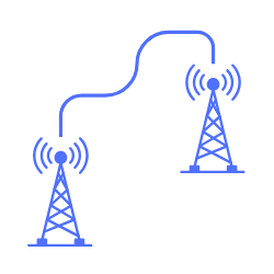
Radio line of sight is the clear path a radio wave needs between two antennas, and it reaches further than the line your eye would draw because the atmosphere bends the wave gently back towards the ground. The lower atmosphere is denser near the surface and thins with height, so its refractive index falls with altitude and a horizontal wave curves downward, following the curve of the Earth for a while instead of flying off into space. The effect is to push the horizon out beyond the optical one.
Engineers model this not by tracking the curved ray, but by a neat trick. You pretend the ray travels in a straight line over an Earth with a larger radius than the real one, so that the geometry becomes simple again. The multiplier on the Earth radius is the k-factor, and in a standard atmosphere it is about 4/3. With that in hand, the distance to the radio horizon from an antenna of height h in metres is:
d (km) ≈ 4.12 · √h
For two antennas the horizons add, so the maximum line of sight distance is 4.12 times the sum of the square roots of the two heights. That single rule, and an understanding of how the k-factor can change, carries most of what you need to judge whether a hop will see itself.
Why Radio Sees Further Than the Eye
Like visible light, radio waves travel in straight lines through a uniform medium, but the lower atmosphere is not uniform. Pressure, temperature and water vapour all decrease with height, and together they make the refractive index of the air fall as you climb. A wavefront travelling horizontally therefore has its top moving through slightly thinner, faster air than its bottom, which tilts the front and bends the whole ray downward, back towards the surface.
The amount of bending depends on how quickly the refractivity falls with height. In an average atmosphere the gradient is gentle and steady, so the ray curves the same way as the Earth but far more gently, which is the condition captured by the familiar 4/3 effective Earth radius. Because it curves more gently than the surface falls away, the ray stays above the ground for longer than a straight line would, and the radio horizon lands further away than the optical one. This is not a rare or exotic effect. It is present on essentially every terrestrial path, which is why a microwave hop routinely closes over distances a surveyor with a theodolite would call beyond the horizon.
The Effective Earth Radius and the K-Factor
Tracking a curved ray over a curved Earth is awkward, so the standard approach straightens the ray and curves the Earth to compensate. If you scale the Earth radius up by a factor k, chosen so that the difference between the ray curvature and the Earth curvature is preserved, the ray becomes a straight line over the enlarged Earth and the trigonometry collapses to something simple. The scaled radius is the effective Earth radius:
R_e = k · R, with R = 6371 km
The k-factor captures the state of the atmosphere. In the standard atmosphere k is 4/3, or about 1.33, the basis of the widely used 4/3 Earth model, which gives an effective radius of roughly 8500 km. A k of 1 would mean no bending at all, the ray tracing a straight optical line. Values of k above 4/3 mean stronger downward bending and a longer reach, and values below 1 correspond to reduced downward bending, so that in sufficiently sub-refractive conditions the ray may even bend upward, shortening the horizon and lifting terrain into the path. The single most important habit in line of sight design is to remember that k is a weather dependent quantity, not a constant, and that the 4/3 value is only an average.
The Radio Horizon Formula
For an antenna at height h above a smooth Earth of effective radius R_e, simple geometry gives the distance to the horizon as the square root of twice the effective radius times the height. Folding in R = 6371 km and k = 4/3, and keeping h in metres and the answer in kilometres, this reduces to the rule worth memorising:
d (km) ≈ 4.12 · √h (standard atmosphere, k = 4/3)
The optical horizon, with no bending at all, uses a smaller constant:
d (km) ≈ 3.57 · √h (k = 1)
The ratio of the two constants, 4.12 against 3.57, is just the square root of 4/3, and it is the numerical size of the refraction bonus. For a link between two antennas, each one sees its own horizon and the grazing point sits somewhere between them, so the maximum line of sight distance is the sum of the two horizon distances:
d_total (km) ≈ 4.12 · (√h₁ + √h₂)
This is the first check on any hop. If the site separation is greater than this figure, the Earth’s curvature blocks the direct path and no amount of transmit power will fix it. You are then looking at taller structures, a repeater, or a different route.
A Worked Example: Two 30 Metre Masts
Consider two 30 metre masts trying to reach each other over flat ground. Using the standard atmosphere rule:
d_total = 4.12 · (√30 + √30) = 4.12 · (5.48 + 5.48) = 4.12 · 10.95 = 45.1 km
So under an average atmosphere the two masts can just see each other at about 45 km. Repeat the calculation with the optical constant to see what the refraction is worth:
d_optical = 3.57 · (5.48 + 5.48) = 39.1 km
The atmospheric bending adds roughly 6 km of reach, about 15 per cent, for free. That is a meaningful margin, but it is also a trap, because it depends on the atmosphere behaving normally. On a night when the refractivity gradient collapses and k drops towards 1 or below, those extra 6 km evaporate and a link sited right at the 45 km limit will fail. A sound design leaves clearance in hand rather than banking the refraction bonus.
The Earth Bulge and Mid-Path Clearance
The horizon rule tells you whether the antennas can see over the curve, but the more useful picture is the Earth bulging up into the middle of the path. Relative to the straight line joining the two antennas, the surface rises to a maximum near the centre of the hop. The bulge height at a point that is d₁ from one end and d₂ from the other, with the two distances measured along the path in kilometres, is:
h_bulge (m) = d₁ · d₂ / (12.74 · k)
The two distances go in as kilometres and the bulge comes out in metres, so take care not to plug metres into that equation. For our 45 km path at k = 4/3, the mid-point sits 22.5 km from each end, so:
h_bulge = 22.5 · 22.5 / (12.74 · 1.33) = 506 / 16.99 = 29.8 m
The Earth bulges up nearly 30 metres in the middle of a 45 km hop, which is why two 30 metre masts are on the edge of seeing each other. This is also the number that reacts most sharply to the k-factor. Halve k and the bulge doubles, which is exactly how a path that clears comfortably in the afternoon can be blocked by the Earth itself under a sub-refractive night sky.
Line of Sight Is Not Enough: Fresnel Clearance
Clearing the terrain by a whisker is not the same as a healthy path, because a radio wave is not a pencil-thin ray. It spreads through a family of ellipsoidal Fresnel zones around the direct line, and obstacles that intrude into the first Fresnel zone rob the link of signal even when the direct line is technically clear. The usual rule is to keep at least 60 per cent of the first Fresnel zone free of obstruction, and ideally the whole of it, on top of the Earth bulge.
That means the real clearance requirement at mid-path is the Earth bulge plus roughly 60 per cent of the first Fresnel radius plus the height of any terrain or clutter there. A path can pass the bare line of sight test and still be a poor link because a hill, a tree line or a building sits inside the Fresnel zone. The full method, and why 60 per cent is the number that matters, is set out in path loss, Fresnel zones and the 80 per cent rule.
The K-Factor Is Not Constant
The greatest risk in line of sight design is treating k = 4/3 as a fixed fact. It is only a long term average, and the real atmosphere varies around that average:
- Sub-refraction (k below 1). On clear, dry nights the refractivity gradient can flatten or reverse, the ray bends less or even upward, the Earth bulge grows, and terrain rises into the path. A link designed only for 4/3 can fade or drop out in these conditions.
- Super-refraction and ducting (k large or negative). Strong temperature inversions, common over water and in the tropics, bend the ray hard downward. This can extend range dramatically but also traps energy in ducts and sets up deep multipath fading and interference from distant sites.
The professional habit is to design for the average but verify the path clears under a worst case low k as well. A common rule is to require full first Fresnel clearance at k = 4/3 and at least 60 per cent clearance at a low k value appropriate to the region, so the link survives a sub-refractive event rather than merely working on a calm day. Many microwave design standards check the path at a k of about 0.67, representing a severe sub-refractive atmosphere that occurs infrequently but is decisive for high availability links. The link planner profiles the whole path against terrain and lets you test clearance across a range of k values, which is the only reliable way to catch a hop that passes at 4/3 and fails at 0.67.
Common Line of Sight Mistakes
- Using the optical horizon. The 3.57 constant ignores atmospheric bending and understates the reach of a real radio path by about 15 per cent. Use 4.12 for a standard atmosphere unless you are deliberately checking a no-bending worst case.
- Treating k as a constant. The 4/3 value is an average, not a guarantee. A path designed only for 4/3 can be blocked by a growing Earth bulge when k falls on a clear night.
- Confusing line of sight with Fresnel clearance. Just clearing the terrain leaves the first Fresnel zone obstructed and the link weak. Budget the Earth bulge plus 60 per cent of the first Fresnel radius, not just the direct line.
- Forgetting antenna height above the mast base. The h in the formula is the height of the antenna above the reflecting surface, which includes the ground elevation at the site, not just the structure height. On a hilltop the effective height is much greater than the mast.
- Ignoring clutter. Trees and buildings at mid-path add to the required clearance just as terrain does, and they can grow over the life of a link. Leave headroom for vegetation.
Frequently Asked Questions
What is radio line of sight? Radio line of sight is the clear, unobstructed path a radio wave needs between two antennas. It reaches further than optical line of sight because the atmosphere bends radio waves gently back towards the Earth, pushing the radio horizon past the visible one. A true radio line of sight path also needs its first Fresnel zone kept clear, not just the direct ray.
Why is the radio horizon further than the visual horizon? Because the lower atmosphere thins with height, its refractive index falls with altitude, and a horizontal radio wave bends downward and follows the curve of the Earth for longer than a straight line of light would. In a standard atmosphere this extends the horizon by about 15 per cent, modelled by scaling the Earth radius by the 4/3 k-factor.
What is the k-factor in radio propagation? The k-factor is the multiplier applied to the true Earth radius to give an effective Earth radius, over which the bent radio ray can be treated as a straight line. A standard atmosphere has k of about 4/3. Values above 4/3 mean stronger downward bending and longer reach, and values below 1 mean the ray bends upward, shortening the horizon and lifting terrain into the path.
How do you calculate the radio horizon? For a standard atmosphere, the distance to the radio horizon in kilometres is about 4.12 times the square root of the antenna height in metres. For a link between two antennas, add the two horizon distances, so the maximum line of sight range is 4.12 times the sum of the square roots of the two heights.
Is line of sight enough for a good radio link? No. A bare line of sight clears the terrain but leaves the first Fresnel zone obstructed, which still costs signal. A reliable path keeps at least 60 per cent of the first Fresnel zone clear, on top of the Earth bulge, and holds that clearance even when the k-factor drops under sub-refractive conditions.
What happens when the k-factor changes? When k falls below its average, the Earth bulge grows and terrain rises into the path, which can fade or drop a link that only just cleared at 4/3. When k rises sharply, ducting can extend range but also cause deep multipath fading and long range interference. Sound designs verify clearance at both the average and a worst case low k.
Build it in noIM₃
The link planner profiles a real path against terrain, works out the Earth bulge and Fresnel clearance at any k-factor, and tells you whether a hop truly closes rather than just looking plausible on a map. The Fresnel zone calculator sizes the clearance you need at mid-path, and the FSPL calculator gives the free space loss once the geometry is sound. Where the ground reflects strongly, the two-ray ground reflection calculator shows how the reflected ray interferes with the direct one.
Key Takeaway
Radio line of sight reaches further than optical line of sight because the atmosphere bends radio waves back towards the Earth, an effect captured by scaling the Earth radius with a k-factor of about 4/3. The radio horizon is roughly 4.12 times the square root of the antenna height in metres, and for a two ended link the horizons add. Clearing the Earth bulge is only the start, because a real path also needs its first Fresnel zone kept 60 per cent clear, and it needs to hold that clearance when the k-factor drops on a clear night. Design for the average atmosphere, verify against the worst case, and leave headroom rather than banking the refraction bonus.