What Size Generator Do You Need?
Start with the equipment that must run together, calculate its real power in kW and apparent power in kVA, then check the generator’s duty rating, motor starting capability, site conditions and fuel requirement. A generator must satisfy each of those checks.
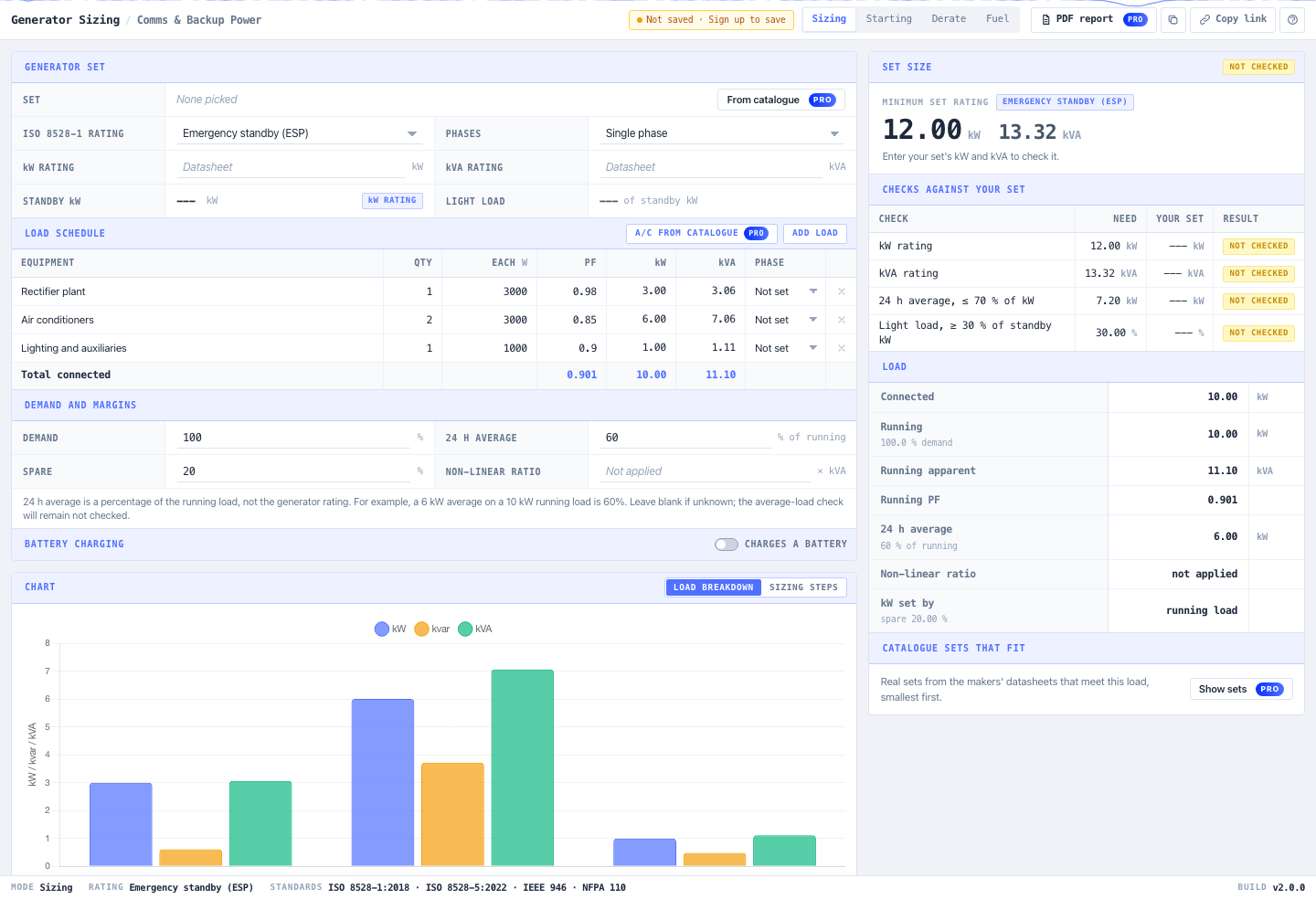
For the example below, a communications hut draws 10.00 kW and 11.10 kVA. With 20% growth allowance, the initial minimum becomes 12.00 kW and 13.32 kVA. Those figures begin the selection process; they do not establish that a particular set can start the air conditioning or deliver its rating at a hot, elevated site.
Open the noIM₃ Generator Sizing Calculator to follow along. The manual calculations run without an account. Pro adds equipment catalogue selection, saved projects and PDF reports.
Build a Load Schedule from Electrical Input Power
In the Sizing tab, replace the example rows with the following illustrative equipment. These are teaching inputs, not specifications for a real installation.
| Equipment | Quantity | Power each, W | Power factor | Total kW |
|---|---|---|---|---|
| Rectifier plant, including its normal DC load | 1 | 3000 | 0.98 | 3.00 |
| Air conditioners | 2 | 3000 | 0.85 | 6.00 |
| Lighting and auxiliaries | 1 | 1000 | 0.90 | 1.00 |
| Total | 10.00 |
Use electrical input watts. An air conditioner’s cooling capacity is not its electrical consumption, and a motor’s shaft-output kW needs an efficiency correction before it becomes electrical input. Count the rectifier’s downstream equipment within its input load, rather than adding the same equipment again.
For this example, select Single phase and leave battery charging off. If your installation uses a three-phase generator, select that instead and assign each load to its actual phase; the most heavily loaded phase can increase the required set size even when the total kVA looks acceptable.
Enter these settings:
| Calculator field | Example input | Meaning |
|---|---|---|
| ISO 8528-1 rating | Emergency standby (ESP) | This example supplies backup power |
| Demand | 100% | All listed equipment can run together |
| 24 h average | 60% | Assumed average of 6 kW, as a percentage of the 10 kW running load |
| Spare | 20% | An explicit allowance for future load |
| Non-linear ratio | Leave blank | No manufacturer-specified multiplier is assumed here |
| Set kW and kVA ratings | Leave blank initially | Calculate the requirement before checking a candidate |
The average-load input is a percentage of the running load, not of the generator rating. Base your own input on the expected operating profile. Leaving it blank means the average-load check is not assessed.
Read the kW and kVA Results
For an individual load, kVA = kW ÷ power factor. The calculator combines the schedule’s real and reactive power separately, using a lagging-power-factor model:
- P = sum of equipment kW
- Q = sum of kW × √(1/PF² − 1)
- S = √(P² + Q²)
Running this example through the calculator’s calculation engine gives:
| Result | Value |
|---|---|
| Running real power, P | 10.00 kW |
| Reactive power, Q | 4.81 kvar |
| Running apparent power, S | 11.10 kVA |
| Combined power factor | 0.901 |
| Minimum set kW, including 20% spare | 12.00 kW |
| Minimum set kVA, including 20% spare | 13.32 kVA |
For example, the air conditioners contribute 6 ÷ 0.85 = 7.06 kVA. Adding every row’s kVA directly would give 11.23 kVA; combining P and Q gives 11.10 kVA because the power factors differ.
This is the calculator’s load model. For non-linear rectifier or UPS loads, obtain the generator compatibility requirements from the equipment and set manufacturers. Enter their non-linear kVA ratio where applicable; a power-factor entry alone does not assess harmonic distortion.
Check the Duty Rating and Average Load
A set’s standby and prime ratings are different operating commitments. Cummins’ guide to ISO 8528 generator ratings describes ESP for emergency backup and PRP for variable-load prime operation, with a 70% average-load limit over the relevant 24-hour operating period. Confirm the chosen set’s permitted hours and load profile with its manufacturer.
For ESP and PRP, the calculator uses:
Minimum kW = max(running kW, average kW ÷ 0.70) × (1 + spare fraction)
At our assumed 6 kW average, 6 ÷ 0.70 = 8.57 kW. The 10 kW running requirement is larger, so the minimum remains 10 × 1.20 = 12.00 kW.
Now change 24 h average to 90%. The average becomes 9 kW, and the result changes to:
9 ÷ 0.70 × 1.20 = 15.43 kW
The kVA minimum remains 13.32 kVA because the running equipment has not changed. This is why both ratings matter.
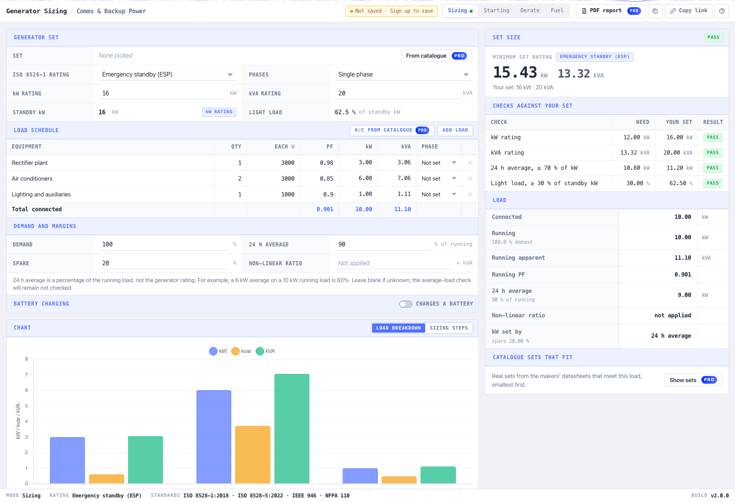
Restore the average to 60% for the remaining example. Enter an illustrative candidate rated 16 kW and 20 kVA for the selected duty. It passes this example’s sizing checks. It is still a candidate until the remaining checks are complete; these ratings do not identify or recommend a particular product.
Check the Air Conditioner Start
Open Starting and assess one air conditioner starting while the other equipment is running. Select the air-conditioner row as the motor. The tool removes one unit from that row for the start calculation, leaving the other air conditioner and the remaining equipment as 7 kW of background load.
For a calculation example, use 3 kW electrical input, 0.85 power factor and an assumed locked-rotor current ratio of 6 with Direct on line starting. The motor’s running apparent power is 3 ÷ 0.85 = 3.53 kVA, and the calculated starting demand is:
Starting kVA = 3.53 × 6 = 21.18 kVA
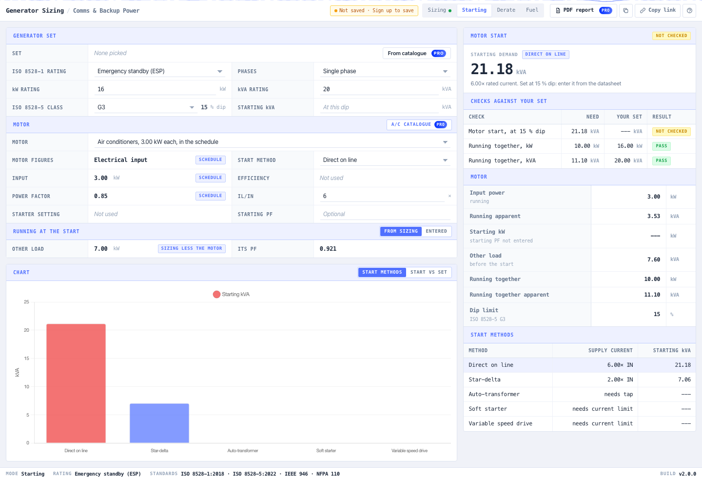
The ratio of six is illustrative. Replace it with the compressor or motor manufacturer’s data; an inverter-driven air conditioner may behave differently.
Compare that demand with the generator’s published motor-starting kVA at the permitted voltage dip. Its 20 kVA running rating does not answer that question. Keep the other running loads in the assessment and ask the supplier to confirm the complete load step, voltage recovery and frequency response. Cummins’ generator application manual explains why initial voltage dip and recovery both matter.
If starting capability is unknown, leave it blank: the tool correctly leaves that check unassessed. Only compare alternative starting methods that the motor and driven equipment support.
Include Battery Recharge and Site Derating
A communications site’s batteries may be depleted when the generator starts. If recharge is additional to the rectifier load already entered, enable Charges a battery and enter the charging voltage, current limit, efficiency and power factor. The calculator adds the recharge input demand to the schedule. Avoid counting recharge twice if your original rectifier figure already includes it.
Next, open Derate. Use the sizing result as the site requirement and enter the altitude, ambient temperature and the selected set’s published derating figures. If you change the load schedule or charging assumptions, carry the revised requirement through this check.
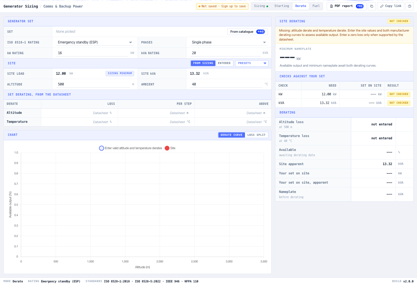
For perspective, if a manufacturer confirms that only 90% of nameplate output is available at the site, supplying our initial 12.00 kW and 13.32 kVA requirement would need at least 13.33 kW and 14.80 kVA at reference conditions. That 90% is an illustration, not a default derating factor. Use the actual engine and alternator limits for the proposed set.
Altitude, temperature, phase arrangement and acceptable load-step dips are selection inputs identified in Cummins’ generator sizing guide. A larger nameplate alone does not settle all of them.
Use the Fuel Tab to Calculate Autonomy
Fuel use comes from the selected set’s fuel table. To demonstrate the Fuel tab, use these deliberately illustrative figures for the 16 kW candidate; replace them with its actual datasheet values before making a fuel plan.
| Load | Example fuel consumption |
|---|---|
| 25% | 2 L/h |
| 50% | 3 L/h |
| 75% | 4 L/h |
| 100% | 5 L/h |
Enter 16 kW rated output, 62.5% load, 100 L usable fuel and a 24-hour target. Leave charging duration blank for this example. The 62.5% load represents 10 ÷ 16 × 100; it assumes the full 10 kW running load persists throughout the fuel calculation, conservatively exceeding the earlier 6 kW average.
The tool interpolates to 3.50 L/h, giving:
- Runtime on 100 L usable fuel: 28.57 hours
- Usable fuel for 24 hours: 84.00 L
- Nominal tank for that target, with 95% fill limit and 5% unusable capacity: 93.33 L
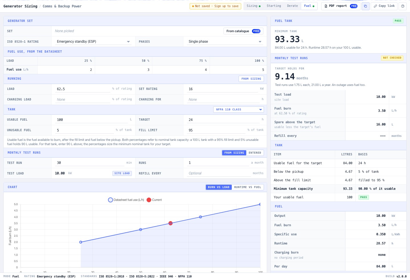
The tank calculation is 84 ÷ (0.95 − 0.05). Both percentages refer to nominal capacity. A nominal 100 L tank would therefore provide 90 L usable under those assumptions, rather than the 100 L entered in the runtime example.
These results exclude a separate operational reserve. Add the project’s reserve and refuelling allowances, and include any recharge period or scheduled test runs when evaluating your actual autonomy.
Keep the Calculation with the Selection
Use Copy results to record each mode’s outputs and Copy link (with a free account) to retain the inputs for review. Pro users can save a project, select equipment from the catalogue and download a PDF report.
For this worked example, the starting point is 12.00 kW and 13.32 kVA, with a 16 kW / 20 kVA candidate passing the initial sizing checks. Motor starting and site derating still need the candidate’s data. Record those remaining checks alongside the load schedule so that a sizing pass is not mistaken for a completed generator selection.
Open the Generator Sizing Calculator and enter your site loads.
Frequently Asked Questions
Can I size a generator by adding up watts?
Adding the watts establishes the real running load. You also need the apparent load in kVA, duty and average-load checks, motor starting capability and site derating. The worked 10 kW schedule here needs at least 12.00 kW and 13.32 kVA with its stated growth allowance, before the remaining checks.
Is a 20 kVA generator always a 16 kW generator?
No. That pairing corresponds to a rated power factor of 0.8. Read both ratings from the selected set’s datasheet for the intended duty, voltage and phase arrangement, and enter them separately.
How much spare capacity should I add?
Use an allowance justified by planned additions and uncertainty in the load schedule. This article uses 20% to demonstrate the calculator; it is not a universal design requirement. Check the proposed set’s acceptable light-load operation as well as its maximum output.
Why does the calculator say a check is not assessed?
A required input may be missing. For example, a motor-start calculation needs the set’s starting capability at the selected voltage dip before it can judge that capability. Supply the relevant datasheet figures rather than treating an unassessed check as a pass.