
← All insights
Insights · Topic
Articles on RF Engineering
Every noIM₃ article on RF Engineering, newest first. Written by engineers, for engineers.
● 30 articles Page 4 of 5
 Newest
 RF Engineering What Is Passive Intermodulation (PIM) and How to Prevent It? Passive intermodulation, or PIM, is interference a radio system makes for itself when two or more strong transmit signals mix in a passive part that is not perfectly linear, such as a connector, cable joint or antenna. The new signals it creates can fall straight into the receive band and quietly desensitise the receiver. This guide explains what PIM is, the formula for where its products land, a worked cellular example, how it is measured in dBc, what causes it including the rusty bolt effect, and the practical steps that keep it off a site.
 RF Engineering What Is Fade Margin and How Much Do You Need? Fade margin is the number of decibels by which the received signal sits above the receiver's usable threshold, the reserve a radio link holds to ride out multipath, rain and atmospheric fading without dropping out. This guide gives the formula, a worked example, the link between fade margin and availability, why each extra nine of uptime costs about 10 dB in the multipath regime, how rain rewrites the rules above 10 GHz, how much margin Australian paths actually need, and the practical ways to buy more of it.
 RF Engineering What Is EIRP? EIRP vs ERP and How to Calculate It EIRP is the power a perfect isotropic antenna would have to radiate to match what your real antenna sends along its main beam. You get it by adding the transmitter power and the antenna gain, then subtracting the feeder loss. Here is the formula, how EIRP differs from ERP, a worked example, and the licence limits and safety distances that all depend on it.
 RF Engineering What Is the Noise Floor? Thermal Noise, SNR and Receiver Sensitivity Explained The noise floor is the faint thermal noise present in every receiver, the level a wanted signal has to rise above to be decoded. At room temperature it starts at −174 dBm per hertz, then climbs with bandwidth and the receiver noise figure. Add the signal to noise ratio your modulation needs and you have the receiver sensitivity. Here is where −174 dBm/Hz comes from, the noise floor formula with a reference table, how noise figure and SNR fit in, and a worked example that turns into a sensitivity figure.
 RF Engineering How to Calculate an RF Link Budget: A Step by Step Guide with a Worked Example A link budget adds every gain and subtracts every loss between a transmitter and a receiver to predict the received power, then compares it against the receiver sensitivity to see whether the link will work. Here is the formula, an at a glance budget table, a worked example for a 5.8 GHz point to point link, and the engineering considerations, fade margin, propagation and noise, that decide whether the design survives in service.
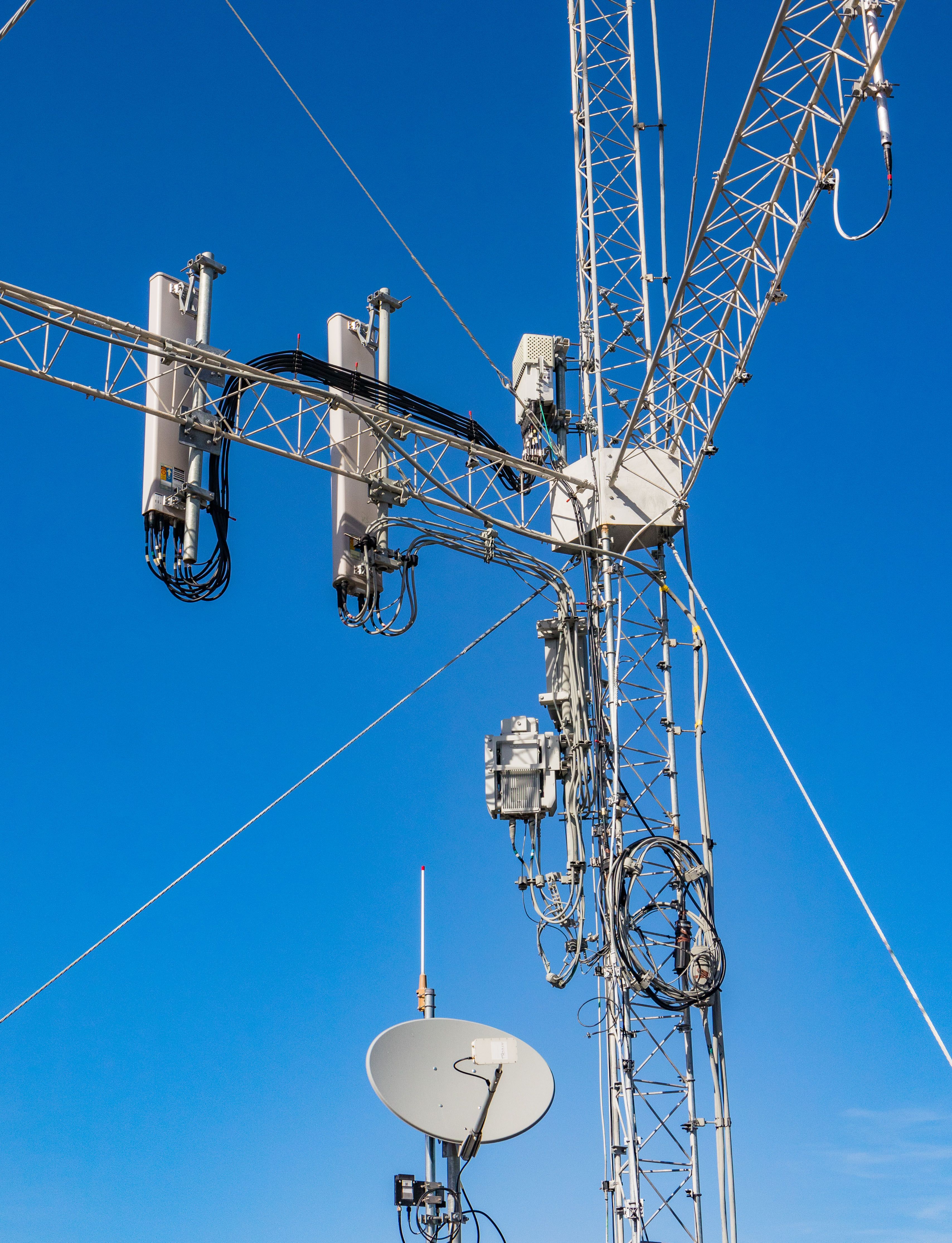 RF Engineering dBm to Watts, dBi vs dBd and dBc: Every RF Decibel Explained (with Conversion Tables) 0 dBm is 1 mW and +30 dBm is 1 watt, so every 10 dB is a tenfold change in power and every 3 dB roughly doubles or halves it. Here is what dB, dBm, dBW, dBi, dBd and dBc each mean, how to convert dBm to watts in both directions, a full conversion table, the dBi to dBd offset, EIRP, and the mistakes that trip people up.