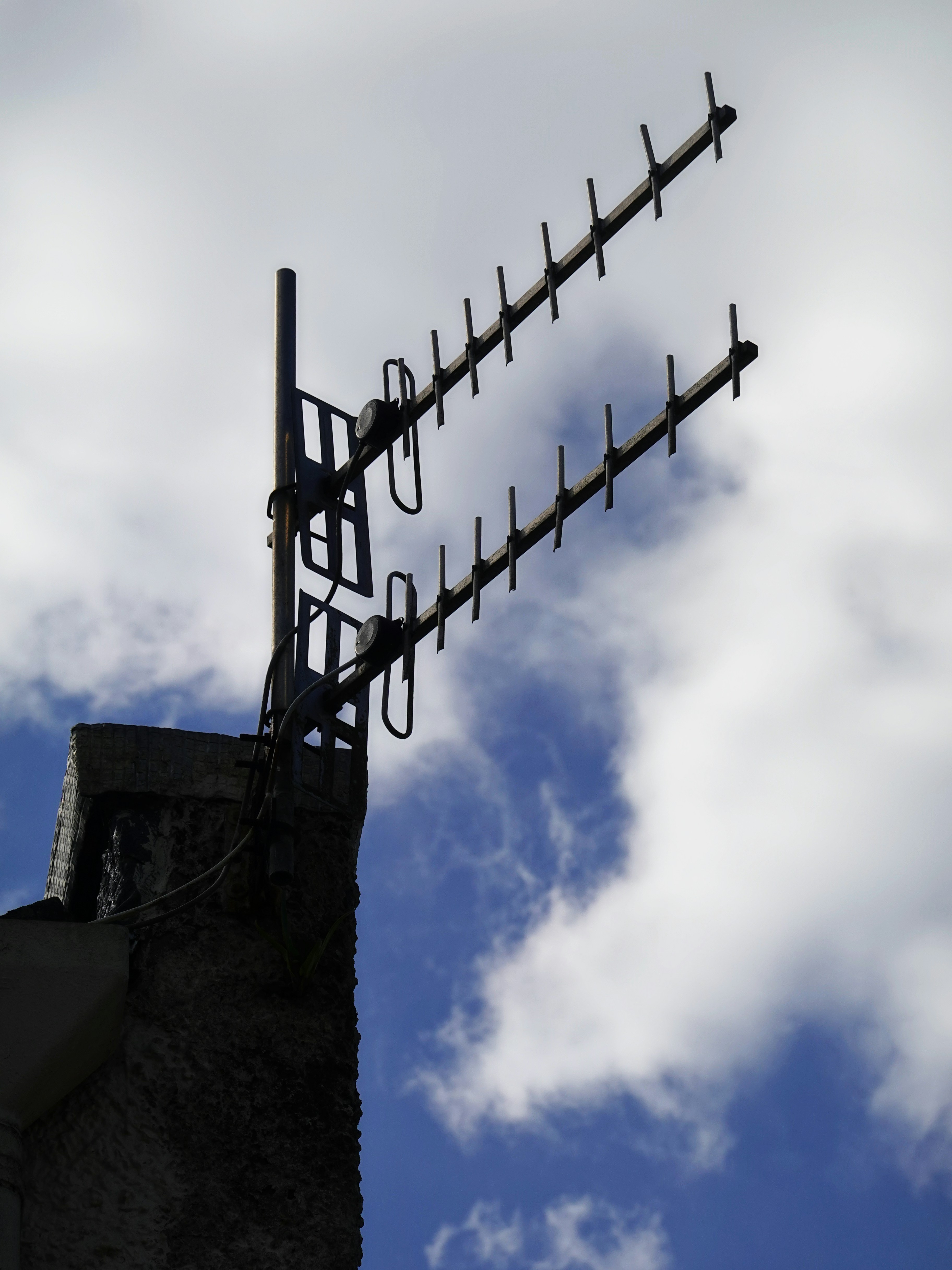
The Short Answer
Antenna gain is a measure of how effectively an antenna concentrates radio energy in a particular direction, compared with a reference antenna that radiates equally in every direction. It is expressed in decibels.
The crucial thing to understand is that gain is not amplification. A passive antenna has no power supply and adds no energy, so it cannot make a signal stronger the way an amplifier does. What it does instead is redistribute the fixed power it is fed, taking energy that would have gone in useless directions and pushing it into the direction you care about.
Because gain is a comparison, it always needs a reference, and there are two in common use. The first is the isotropic radiator, a theoretical point source that radiates equally in all directions, and gain measured against it is written in dBi. The second is the half wave dipole, a real and buildable antenna, and gain measured against it is written in dBd. The two scales are locked together by a fixed offset:
Gain (dBi) = Gain (dBd) + 2.15
The 2.15 dB gap exists because the dipole is not itself isotropic. It already focuses energy slightly, with 2.15 dBi of gain of its own, so quoting a figure against the dipole always reads about 2.15 dB lower than the same antenna quoted against isotropic. Get that offset straight and most antenna data sheets suddenly make sense. Gain is also reciprocal, which means an antenna has the same gain whether it is transmitting or receiving, so the number is added at both ends of a link.
The rest of this guide builds up from that idea. The main thread is written to be read without heavy maths, and the few deeper derivations are tucked into optional boxes you can open only if you want them.
Gain Is Focus, Not Power
The most useful mental model for antenna gain is a torch with an adjustable reflector. The globe puts out a fixed number of watts no matter how you set it. With the reflector wound out to a floodlight, that light is spread thinly over a wide area and nothing is especially bright. Wind the reflector in to a tight spotlight and the same watts are concentrated into a narrow cone, so that cone is far brighter, while everything outside it goes dark.
The torch has not become more powerful. It has become more focused, and gain is simply the measure of that focus.
An antenna does exactly the same thing with radio waves. A high gain antenna does not create energy, it borrows brightness in the wanted direction by going dark everywhere else. This is why gain is a passive property and why it obeys conservation of energy. Every decibel of gain in the main beam is paid for by energy removed from the directions the antenna is not pointing.
There is one refinement worth naming. The pure geometric focusing of an antenna is called its directivity, while the gain quoted on a data sheet also accounts for the small losses inside the antenna, so gain is always a little lower than directivity. For a link budget, gain is the number you want, because the losses are already baked in.
Going deeper: directivity, gain and efficiency
Directivity describes the focusing alone, as if the antenna were lossless. Real antennas dissipate a little of the power fed to them as heat in their conductors and dielectrics, and the fraction that survives to be radiated is the radiation efficiency. Gain is simply directivity multiplied by that efficiency:
Gain = Directivity × Radiation efficiency
For a well made antenna the efficiency is high, often above 90 per cent, so the two figures sit within a fraction of a decibel of each other. The gap matters most for physically small or lossy antennas, where a large directivity can be undercut by poor efficiency, which is one reason a tiny antenna rarely delivers the gain its size might suggest. A data sheet that quotes directivity rather than gain is quietly flattering the antenna, so it is always worth checking which of the two you are reading.
dBi vs dBd: The Two Reference Antennas
Almost every mistake people make with antenna gain comes from mixing up the two reference scales, so it is worth being precise about each one.
The isotropic radiator is a mathematical fiction, a single point that radiates power equally in every direction to form a perfect sphere. No such antenna can be built, because a real radiator always has some structure and therefore some directionality, but the isotropic source is a clean and unambiguous baseline. By definition it has a gain of 0 dBi, and every dBi figure states how much better an antenna does than that perfect sphere in its best direction.
The half wave dipole is a real antenna, a straight conductor a half wavelength long, and it is the traditional reference for the broadcast and land mobile world. It is not isotropic, because it radiates in a doughnut shape with nothing off the ends, so it already has 2.15 dBi of gain built in.
Gain quoted against the dipole is written in dBd, and the conversion follows directly from that 2.15 dBi head start:
- To convert dBd to dBi, add 2.15: dBi = dBd + 2.15
- To convert dBi to dBd, subtract 2.15: dBd = dBi − 2.15
So a whip advertised as 5 dBd is really 7.15 dBi, and a panel advertised as 17 dBi is really about 14.85 dBd. The numbers describe the same physical antenna, they are just measured against different rulers.
The trap is comparing two products where one vendor quotes dBi and the other quotes dBd, because the dBd product will look 2.15 dB worse than it really is, or the dBi product 2.15 dB better. Always convert both figures to the same reference before you compare them, and when in doubt assume a bare dB with no letter means dBi, since that is now the more common convention.
A Worked Example: Turning Gain Into EIRP
Gain earns its keep the moment you drop it into a real calculation, and the clearest place to see that is the effective isotropic radiated power, or EIRP, of a transmitter. Take a Yagi antenna advertised as 15 dBd, fed by a 10 watt transmitter through a feeder run that costs 2 dB.
First put the gain on the isotropic scale so it matches everything else: 15 dBd + 2.15 = 17.15 dBi. Next put the transmit power into dBm, since 10 watts is 40 dBm. Now the EIRP is simply the transmit power, minus the feeder loss, plus the antenna gain:
EIRP = 40 − 2 + 17.15 = 55.15 dBm
That is about 327 watts of effective radiated power in the direction the Yagi is pointing, from a transmitter that only produces 10 watts.
The antenna has not manufactured those extra watts. It has concentrated the 8 watts that survive the feeder into a narrow beam, so a receiver sitting in that beam sees the same signal it would have seen from a 327 watt isotropic source. This is exactly why gain is so valuable, and why regulators cap EIRP rather than raw transmitter power, because it is the focused power that actually reaches other users. The full method, including ERP and the difference between the two, is set out in what is EIRP, EIRP vs ERP and how to calculate it.
Gain and Beamwidth: Two Faces of One Trade
You cannot increase gain without narrowing the beam, and this is the single most important trade in antenna selection. Since a passive antenna only redistributes a fixed amount of power, the only way to make the main beam more intense is to squeeze it into a smaller solid angle. High gain and narrow beamwidth are therefore the same fact described two different ways.
Beamwidth is normally quoted as the half power beamwidth, the angle between the two points on either side of the main lobe where the radiated power has fallen to half its peak, which is 3 dB down. An antenna has a beamwidth in the horizontal plane, called the azimuth beamwidth, and one in the vertical plane, called the elevation beamwidth, and the two are often different. A sector panel on a mobile tower might be wide in azimuth to cover a slice of the horizon but narrow in elevation to avoid wasting power into the sky and the ground.
The relationship between gain and the two beamwidths can be captured with a simple approximation. For a beam that is θ_az degrees wide in azimuth and θ_el degrees wide in elevation, a realistic estimate of the usable gain is:
Gain (dBi) ≈ 10 · log₁₀(26000 / (θ_az · θ_el))
As a worked example, a dish with a symmetric beam that is 3 degrees wide in both planes has a gain of about 10 · log₁₀(26000 / (3 · 3)) = 10 · log₁₀(2889), which is roughly 34.6 dBi.
Turn that around and the message is stark. To get 35 dBi of gain you must accept a beam only about 3 degrees wide, which is narrower than the width of your thumb held at arm’s length. That antenna will deliver a superb signal to whatever it is aimed at and almost nothing to anything a few degrees off to the side, so it must be mounted rigidly and aligned carefully, and it is useless for covering a wide area. The beamwidth calculator lets you move between gain and beamwidth directly so you can see the cost of every extra decibel.
Going deeper: where the beamwidth constant comes from
A full sphere contains about 41253 square degrees. If an antenna spread its power evenly across a rectangular beam and radiated nothing outside it, its directivity would be that whole sphere divided by the solid angle of the beam:
D ≈ 41253 / (θ_az · θ_el)
with the two beamwidths in degrees. That is the ideal, lossless figure. Real antennas fall short of it for two reasons: they have some loss, which the efficiency accounts for, and they never radiate cleanly inside the main beam alone, because some power always leaks into the side lobes. To fold both effects into one quick estimate, engineers replace the 41253 with a smaller constant, commonly around 26000, which is the value used in the main text. The exact constant varies with the antenna type and how sharply its pattern rolls off, so treat any single figure as an estimate good to a decibel or two rather than an exact law.
How Aperture Sets the Ceiling for Dishes
For an aperture antenna such as a parabolic dish, gain comes from physical size and frequency, and the relationship is worth carrying in your head. The gain of a dish rises with its collecting area and with the square of the frequency, because a shorter wavelength lets a given area form a tighter beam. A practical form of the parabolic gain equation, for a dish of diameter D in metres at a frequency f in gigahertz and a typical aperture efficiency of about 55 per cent, is:
G (dBi) ≈ 17.8 + 20 · log₁₀(D) + 20 · log₁₀(f)
As a worked example, a 1.2 metre dish at 6 GHz has a gain of 17.8 + 20 · log₁₀(1.2) + 20 · log₁₀(6) = 17.8 + 1.6 + 15.6, which is about 35 dBi, matching the 3 degree beam from the previous section.
Because both diameter and frequency appear as 20 · log₁₀ terms, they carry the same 6 dB rule that governs free space path loss:
- Double the dish diameter, add 6 dB. A 2.4 metre dish has 6 dB more gain than a 1.2 metre dish at the same frequency.
- Double the frequency, add 6 dB. The same dish delivers 6 dB more gain at 12 GHz than at 6 GHz.
That second rule is the exact counterpart of the frequency penalty in free space path loss. Higher frequencies suffer more path loss because a fixed gain antenna has a smaller aperture, but a fixed size dish gains 6 dB per octave to match, which is precisely why microwave and millimetre wave links use dishes. The antenna recovers what the path loss formula appears to take away. The parabolic antenna calculator works this relationship in both directions, from size and frequency to gain and back again.
Reading a Radiation Pattern
A single gain figure only tells you the peak value in the best direction. To understand how an antenna behaves everywhere else you need its radiation pattern, the plot that shows relative radiated power as a function of angle. Patterns are usually drawn as two polar cuts, one in the azimuth plane looking down from above and one in the elevation plane looking from the side, and learning to read them is a core skill.
The features to look for are always the same:
- The main lobe is the beam of maximum radiation, and its width at the 3 dB points is the half power beamwidth. This is where the quoted gain lives.
- Side lobes are the smaller beams either side of the main lobe, where the antenna radiates power you would rather it did not. They are quoted relative to the main lobe, so a side lobe level of −20 dB means the strongest side lobe is a hundred times weaker than the main beam. Low side lobes matter enormously for interference, because a side lobe pointed at a neighbouring system is a path for unwanted energy in both directions.
- The back lobe is radiation out the rear of the antenna, and the ratio of forward gain to this rearward radiation is the front to back ratio. A high front to back ratio is what lets you reuse a frequency behind a directional antenna, and it is a headline number for panels and Yagis.
- Nulls are the angles where radiation drops close to zero, between the lobes. They can be used deliberately, for instance by tilting a base station antenna so a null falls on a distant co channel site to suppress interference.
Reading a pattern properly stops you from being fooled by the peak gain alone. Two antennas with the same 15 dBi peak can behave completely differently in a crowded band if one has clean, low side lobes and the other sprays energy in every direction. In an interference limited network the shape of the pattern often matters more than the peak, which is why pattern quality, not just gain, drives antenna selection.
Where Antenna Gain Fits in a Link Budget
In a link budget, antenna gain appears as two separate line items, one for each end, and both are added to the sum because both antennas focus energy along the path. The received power on a simple link is the transmit power, plus the transmit and receive antenna gains, minus the feeder and connector losses, minus the path loss:
P_rx (dBm) = P_tx + G_tx + G_rx − L_feeder − FSPL
Because gain is reciprocal, the same dish contributes its full gain whether it is sending or receiving, which is why a point to point microwave hop with a good dish at each end can close over enormous distances on modest transmit power.
Gain is very often the cheapest decibel available to a designer, since a larger antenna costs far less than a bigger amplifier or a more sensitive receiver and adds nothing to the running power bill. The catch is always beamwidth. Every decibel of gain narrows the beam and tightens the alignment tolerance, so the practical ceiling on gain is set by how accurately you can point and how stable the mount is, not by the physics.
One warning that trips up beginners is double counting. Free space path loss is defined between two isotropic antennas, so it already assumes the gains are handled separately. The gains go in as their own line items and must never be folded into the path loss term as well, or they are counted twice. The Friis equation calculator works the same relationship from the antenna point of view, and the link budget calculator drops gain, path loss, feeder loss and sensitivity into a full budget so you can see the margin at a glance. The wider method is covered in how to calculate an RF link budget.
Common Antenna Gain Mistakes
- Mixing dBi and dBd. The two scales differ by 2.15 dB, so comparing a dBd figure from one vendor with a dBi figure from another hands one product a phantom 2.15 dB advantage. Convert both to the same reference before comparing.
- Thinking gain amplifies power. A passive antenna has no power supply and creates no energy. It concentrates a fixed input, so every decibel in the main beam is taken from another direction.
- Chasing gain and ignoring beamwidth. High gain means a narrow beam. A 35 dBi dish sees only a few degrees, so it demands rigid mounting and careful alignment and is hopeless for wide area coverage.
- Confusing directivity with gain. Directivity ignores losses, while gain includes efficiency. A data sheet that quotes directivity flatters the antenna, because the real gain is always a little lower once conductor and dielectric losses are counted.
- Reading peak gain as gain everywhere. The quoted figure is the value on boresight, in the centre of the main lobe. A few degrees off axis the gain has already dropped, and by the 3 dB points it is half, so a poorly aimed high gain antenna can perform worse than a modest omnidirectional one.
- Double counting gain in the path loss. Free space path loss assumes isotropic antennas, so the gains belong in their own line items and must not be built into the loss term as well.
Frequently Asked Questions
What is antenna gain in simple terms? Antenna gain is a measure of how well an antenna focuses radio energy in one direction rather than spreading it everywhere, compared with a reference antenna that radiates equally in all directions. It is not amplification, because a passive antenna adds no power of its own. It simply redistributes the power it is fed, concentrating it into the wanted direction by radiating less everywhere else, and gain is the measure of that focus in decibels.
What is the difference between dBi and dBd? Both are units of antenna gain, but they use different reference antennas. dBi compares the antenna with a theoretical isotropic radiator that radiates equally in every direction, while dBd compares it with a real half wave dipole. Because the dipole already has 2.15 dBi of gain of its own, a figure in dBd always reads 2.15 dB lower than the same antenna quoted in dBi.
How do I convert dBd to dBi? Add 2.15 to the dBd figure to get dBi, and subtract 2.15 from a dBi figure to get dBd. So a 5 dBd antenna is 7.15 dBi, and a 12 dBi antenna is about 9.85 dBd. The 2.15 dB offset is fixed, because it is simply the gain of the reference dipole over an isotropic source.
Does a higher gain antenna transmit more power? No. A passive antenna has no power source and cannot increase the total power radiated. A higher gain antenna concentrates the same total power into a narrower beam, so the signal is stronger in the direction the antenna points and weaker everywhere else. The effective radiated power in the beam rises, but the total power leaving the antenna does not.
What is the relationship between gain and beamwidth? Gain and beamwidth are two descriptions of the same thing, and they trade directly against each other. Higher gain always means a narrower beam, because the only way to make the main beam more intense is to squeeze the fixed power into a smaller angle. As a rough guide, a symmetric beam a few degrees wide corresponds to a gain in the mid thirties of dBi, so very high gain antennas must be aimed and mounted with care.
Is antenna gain the same for transmitting and receiving? Yes. Antenna gain is reciprocal, which means an antenna has the same gain and the same radiation pattern whether it is transmitting or receiving. This is why a single gain figure is added at both ends of a link budget, and why a good dish helps just as much on the receive side as on the transmit side.
What is a good antenna gain? It depends entirely on the job. A handheld radio or a base station covering a town wants a low gain, wide beam antenna so it can hear in every direction, often just a few dBi. A long point to point microwave hop wants a high gain dish of 30 dBi or more to reach across tens of kilometres. There is no universally good figure, only the gain that matches the coverage and range the application needs.
Build it in noIM₃
The antenna builder models real antenna geometries and shows the gain and pattern they produce, so you can see the focus and beamwidth trade for yourself. The beamwidth calculator moves directly between gain and half power beamwidth, and the parabolic antenna calculator turns dish size and frequency into gain. When you are choosing between products, the antenna selector compares candidates on a like for like basis, the EIRP calculator turns gain and transmit power into radiated power for a compliance check, and the Friis equation calculator carries the whole thing through to a received power.
Key Takeaway
Antenna gain is focus, not power. A passive antenna radiates a fixed amount of energy and gain simply measures how tightly it concentrates that energy into one direction at the expense of every other. Read every figure against the right reference, remembering that dBi and dBd differ by a fixed 2.15 dB, and never compare the two scales without converting first. Treat gain and beamwidth as one decision rather than two, because every decibel of gain narrows the beam and raises the price you pay in alignment and coverage. Do that, add the gain correctly at both ends of the budget without double counting it in the path loss, and the most misread number on the data sheet becomes one of the most powerful tools you have for closing a link.