VSWR: The Short Answer
A good VSWR is usually 1.5:1 or better, which corresponds to a return loss of about 14 dB and reflects roughly four per cent of the forward power. Most radio systems treat 2:1 as the acceptance limit, because many modern transmitters begin reducing their output power somewhere between 2:1 and 3:1 to protect the final amplifier stage. A perfect match is 1.0:1, where nothing is reflected, and lower is always better. VSWR, return loss, and reflection coefficient are the same measurement written three ways, so once you have one of them you have all of them.
VSWR Quick Reference
| VSWR | Verdict |
|---|
| 1.0:1 to 1.2:1 | Excellent |
| 1.2:1 to 1.5:1 | Very good |
| 1.5:1 to 2.0:1 | Acceptable |
| 2.0:1 to 3.0:1 | Investigate |
| Above 3.0:1 | Problem likely |
These verdicts are general guidance for a transmit system. The right pass mark for any given job is the one set by your equipment specification and licence conditions.
What VSWR Actually Measures
VSWR stands for voltage standing wave ratio. When a signal travels down a feed line and meets a load, such as an antenna, that is not perfectly matched to the line, part of the signal reflects back toward the source. The forward wave and the reflected wave add together along the cable, producing peaks and troughs of voltage that stand in fixed positions. VSWR is the ratio of the highest voltage on that standing wave to the lowest.
If the load is a perfect match, nothing reflects, the voltage is the same everywhere, and the ratio is 1.0:1. The worse the mismatch, the larger the reflection and the bigger the gap between the peaks and the troughs, so the ratio climbs. A total reflection, such as an open circuit or a short circuit, gives an infinite VSWR. In practice the number you read on an analyser is a direct, sensitive measure of how well your antenna and cabling are matched to the radio.
VSWR, Return Loss and Reflection Coefficient
These three figures are one measurement in different clothes. The reflection coefficient, written |Γ|, is the fraction of the signal voltage that bounces back off the mismatch, ranging from zero for a perfect match to one for total reflection. The magnitude of the reflection coefficient is:
|Γ| = (VSWR − 1) / (VSWR + 1)
and the inverse is:
VSWR = (1 + |Γ|) / (1 − |Γ|)
The mismatch ultimately comes from the impedances themselves, where ZL is the load impedance and Z0 the line impedance:
Γ = (ZL − Z0) / (ZL + Z0)
Connecting a 75 Ω load to a 50 Ω line, for example, gives Γ = 25 / 125 = 0.2 and a VSWR of 1.5:1, which is why a 75 Ω device on a 50 Ω system is a textbook source of a mild mismatch. For a purely resistive load like this the reflection coefficient is real and equal to its own magnitude; with a reactive load Γ is complex, and it is the magnitude |Γ| that feeds the VSWR and return loss relationships above.
Return loss is that same reflection expressed in decibels and quoted as a positive number:
RL = 20 · log₁₀(1 / |Γ|)
A larger return loss is better, because it means less of the signal came back. On a vector network analyser the same quantity is usually displayed as S11 in decibels, written as a negative number: an S11 of −14 dB is the same as a return loss of 14 dB and a VSWR of roughly 1.5:1, which is why the two terms are often searched and used interchangeably. The reflected power fraction is simply the square of the magnitude of the reflection coefficient, so |Γ|² of the forward power, and the small amount of forward power given up to the mismatch on the way through is the mismatch loss.
VSWR Conversion Table
| VSWR | Reflection coeff. |Γ| | Return loss | Reflected power | Mismatch loss |
|---|
| 1.0:1 | 0.00 | ∞ | 0% | 0 dB |
| 1.1:1 | 0.05 | 26.4 dB | 0.2% | 0.01 dB |
| 1.2:1 | 0.09 | 20.8 dB | 0.8% | 0.04 dB |
| 1.5:1 | 0.20 | 14.0 dB | 4.0% | 0.18 dB |
| 2.0:1 | 0.33 | 9.5 dB | 11.1% | 0.51 dB |
| 3.0:1 | 0.50 | 6.0 dB | 25.0% | 1.25 dB |
Two things jump out of the table. First, even a fairly poor 2:1 match only reflects about eleven per cent of the power and costs around half a decibel on the way through, which is why VSWR often matters less for raw signal level than people expect. Second, the return loss scale stretches out the good end: the difference between 1.1:1 and 1.5:1 is twelve decibels of return loss, so return loss is the more useful number when you are comparing well matched systems. For professional RF work, return loss and S11 are often preferred over VSWR for exactly this reason, because they give more resolution once the match is already good.
What Is a Good VSWR?
There is no single pass mark, but a few norms hold across most radio work.
- 1.5:1 or better (return loss of 14 dB or more) is the usual target for a transmit antenna system or base station feeder. It keeps reflected power at or below four per cent.
- 2.0:1 (return loss of about 9.5 dB) is a common acceptance limit. Many modern transmitters begin reducing their output somewhere between 2:1 and 3:1 to protect the final amplifier stage, with the exact threshold set by the manufacturer, so 2:1 is often treated as the line between pass and investigate.
- 1.2:1 or better is asked for where every fraction of a decibel counts, such as low noise receive chains, test benches, and precision instrumentation.
- For a receive only path the figure matters far less. Even a 2:1 VSWR costs only about 0.5 dB of mismatch loss, so receive only systems routinely tolerate a significantly higher VSWR than transmit systems, where amplifier protection and reflected power are the real concerns.
The right target is the one your equipment specification and licence conditions call for. Lower is always better, but chasing 1.05:1 on a system that only needs 1.5:1 is effort spent for no real return.
How Much Power Does a High VSWR Waste?
Less than most people assume, at least in terms of signal. A 2:1 VSWR reflects about eleven per cent of the power and costs roughly half a decibel of mismatch loss, which is rarely the thing that makes or breaks a link. The real reasons to care about VSWR are elsewhere.
The first is equipment protection. Reflected power travels back toward the transmitter, where it stresses the output stage and raises voltage and heat at the mismatch point. Most modern transmitters sense this and start reducing their output somewhere between 2:1 and 3:1, so a high VSWR can quietly cost you far more power through foldback than it ever loses to reflection. It is worth being precise about that reflected power, though, because it is not necessarily dissipated straight away. On a low loss line it can be reflected again at the source and sent back toward the load, so the actual reduction in delivered power is described by the mismatch loss rather than by the reflected power figure on its own.
The second reason is diagnosis. VSWR is a fast and sensitive indicator that something physical is wrong, a connector, a length of cable, or the antenna itself, even when the through loss looks small. The third shows up on busy sites: reflections from a poor match can mix with other signals and feed intermodulation products. So you do not chase a low VSWR to recover half a decibel. You chase it because it protects the radio and tells you the system is healthy.
Common Causes of High VSWR
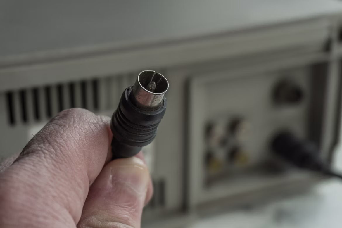
- Connectors. Loose, cross threaded, badly torqued, corroded, or water affected connectors are by far the most common cause, and the first place to look.
- Damaged cable. Kinked, crushed, or water affected coaxial cable shifts the impedance and drives the reflection up.
- The wrong load. A 75 Ω device on a 50 Ω system, or an antenna cut for a different band, will never match well.
- A faulty antenna. Physical damage, ice or snow loading, or corrosion at the feed point all raise the reading.
- Frequency. An antenna only presents a good match across its design band, so VSWR naturally rises toward the band edges even when nothing is wrong.
How to Measure and Fix VSWR
Measure with a vector network analyser or a handheld antenna analyser, and sweep across the operating band rather than reading a single frequency, because the match changes across the band. Read the VSWR, or the S11 trace, at your actual operating frequencies, and note the frequency of the lowest dip to confirm the antenna is tuned where you need it rather than somewhere nearby.
When a reading is high, fix the cheap things first. A distance to fault measurement points to a bad connector or a damaged section along the run, and since connectors cause most faults, reseat, clean, and correctly torque them before you suspect the antenna. Where the mismatch is inherent to the design rather than a fault, a matching network or a correctly specified balun brings the impedance back toward 50 Ω.
Checking VSWR in noIM₃
The VSWR calculator takes whichever of the four numbers you happen to have, VSWR, return loss, reflection coefficient, or a forward and reflected power reading off a meter, and returns the rest, including reflected power and mismatch loss. That turns a field measurement into the figure your specification is written in, whichever way round it is stated.
When the mismatch comes from several places at once, the return loss calculator rolls up the contributions of a connector, a cable, and an antenna into a single system return loss, which is the number that actually reaches the radio. The reflection coefficient calculator ties |Γ| back to the underlying impedance when you need to work from a 50 Ω reference.
Frequently Asked Questions
What is a good VSWR? For a transmit system, 1.5:1 or better is the usual target, and 2:1 is the common acceptance limit. A perfect match is 1.0:1, and lower is always better. Where high precision is needed, such as a low noise receiver, 1.2:1 or better is often specified.
What does a VSWR of 1.5:1 mean? It means the reflection coefficient is 0.2, the return loss is about 14 dB, and four per cent of the forward power is reflected back toward the source. That is generally considered a good, healthy match for a transmit antenna system.
What is the difference between VSWR, return loss and S11? They describe the same mismatch on different scales. VSWR is a ratio starting at 1.0:1 for a perfect match and rising as the mismatch worsens. Return loss is the same reflection in decibels, quoted as a positive number, where a higher value is better. S11 is how an analyser usually shows it, the same figure as a negative number, so an S11 of −14 dB equals a return loss of 14 dB and a VSWR of about 1.5:1.
Does a high VSWR damage a transmitter? It can. Reflected power stresses the output stage and raises heat and voltage at the mismatch, and most modern transmitters reduce their output somewhere between 2:1 and 3:1 to protect the final amplifier stage, with the threshold varying by manufacturer. Keeping the VSWR low protects the equipment and keeps full power flowing forward.
Key Takeaway
VSWR, return loss, and reflection coefficient are a single measurement expressed three ways, so any one of them gives you the other two. A good target is 1.5:1 or better for a transmit system, with 2:1 as the usual acceptance limit and 1.0:1 as perfect. The value matters less for the half a decibel a mismatch costs in signal and more as a fast, sensitive check that your connectors, cable, and antenna are all healthy, and as protection for a transmitter that would otherwise fold its power back.