Fiber Optic Design

Fiber Optic Connector and Splice Loss Calculator

End-to-end fibre link-loss workstation. Build the budget from the physical inventory — multi-segment fibre plant, IEC 61753-1 connector inventory, fusion and mechanical splices, and an optional ITU-T G.671 PLC splitter — and read the total link loss against the design margin, the computed link ORL, and an MMF bandwidth-distance reach check in one view.

Overview

A fibre link either has the loss budget to close or it does not, and the difference is usually a few tenths of a dB spread across every mated connector pair, every splice, and every kilometre of cable. The trouble is that the budget is assembled from a physical inventory that nobody keeps in one place. The feeder, distribution, and drop segments each have their own length and attenuation at the operating wavelength. The connectors are a mix of APC and UPC polishes with different insertion loss and return loss. There are fusion splices and there are mechanical splices, and they behave nothing alike. There may be a PON splitter eating seventeen or more dB on its own. Add it up by hand against a 28 dB Class B+ budget and one transposed digit is the difference between a link that closes and a truck roll.

The noIM₃ Fiber Optic Connector and Splice Loss Calculator builds the budget the way the plant is actually built — from the inventory. Each fibre segment carries an independent length and per-km attenuation that auto-fills from the selected fibre type and wavelength. An IEC 61753-1 connector inventory tracks each connector type, the mated-pair count, and the per-pair insertion loss, with the typical value auto-filled on type selection. Fusion and mechanical splices are counted separately so each population is sized and audited against its own loss and ORL assumption. An optional ITU-T G.671 PLC splitter adds the split-ratio loss with the typical value surfaced inline at pick time and a Worst-case +1 dB toggle for vendor spread.

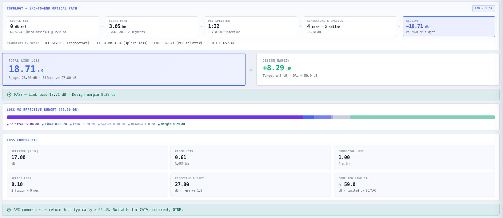
The headline pair reads Total Link Loss against the Design Margin, colour-coded PASS / MARGINAL / FAIL against a configurable minimum target, with the effective budget (max allowable minus the aging and contamination reserve) and the computed link ORL annotated underneath. A six-segment stacked bar makes the budget composition visible at a glance, and the Link Loss Breakdown table itemises every contributor with the standard cited in its notes column. Link ORL is computed by sum-of-reflectances and the limiting connector polish is named. When an MMF fibre type is selected, an IEEE 802.3 bandwidth-distance card checks the current span against the short-reach Ethernet limits — because modal dispersion limits reach regardless of the optical power budget.

Where the PON Optical Budget tool models a single OLT to ONT path against an ITU-T class budget, this tool is the link-budget workstation for any installed fibre plant — PON, enterprise LAN, long-haul SMF, or data-centre MPO. Six link-standard quick-applies (1000BASE-LX through XGS-PON N2) and four preset scenarios drop a full design in with one click so a vendor budget can be verified against an independent IEC 61753-1, ITU-T G.671, and IEEE 802.3 reference. Everything runs in your browser, auto-saves to local storage, and copies out as a structured audit string with a standards citation footer for the project pack.

Capabilities

Topology cascade and standards-in-scope citation

The main column opens with an end-to-end topology view of the optical path — Source (Tx) → Fibre Plant → optional PLC Splitter → Connectors & Splices → Receiver — with per-stage loss surfaced inline and a mode badge identifying the topology class (PON · 1:N when the splitter is enabled, Point-to-Point otherwise). A Standards in Scope row underneath cites IEC 61753-1 for the connector inventory, IEC 61300-3-34 for splice loss, ITU-T G.671 for the PLC splitter when enabled, IEEE 802.3 for MMF reach when an MMF fibre type is selected, and the governing standard for the active fibre type — every standard the current design draws from in one row.

Multi-segment fibre plant with auto-fill attenuation

Build the fibre plant from any number of labelled segments — typical composition is Feeder + Distribution + Drop for FTTH, or a single Trunk for long-haul. Each segment carries an independent length in metres and per-km attenuation in dB/km. Selecting a fibre type and wavelength auto-fills attenuation on every segment using the per-wavelength typical value from the fibre standard, and an individual segment can be overridden when the cable spec or measured OTDR data is known. Six fibre types are exposed — G.652.D (OS2 SMF), G.657.A1, G.657.A2, OM3, OM4, and OM5 — each with per-wavelength attenuation tables.

IEC 61753-1 connector inventory with ORL tracking

Connector inventory rows pick a type from a dropdown (LC/APC, LC/UPC, SC/APC, SC/UPC, FC/APC, FC/UPC, MPO-12, MPO-24, E2000/APC, ST/PC), a quantity in mated pairs, and a per-pair insertion loss in dB. Type selection auto-fills the per-pair loss with the IEC 61753-1 typical value for that connector (Grade A E2000/APC ≤ 0.20 dB, Grade B LC/SC/FC ≤ 0.25–0.30 dB, Grade C ST/PC ≤ 0.50 dB). The minimum ORL of each type (APC ≥ 65 dB, UPC ≥ 45 dB, ST/PC ≥ 40 dB, MPO ≥ 26 dB, E2000/APC ≥ 70 dB) feeds the link ORL computation and the APC / UPC suitability banner.

Fusion and mechanical splice loss (IEC 61300-3-34)

Fusion and mechanical splices are tracked separately so each population can be sized independently and audited against its own loss assumption. Fusion splices are typically 0.02–0.05 dB each (IEC 61300-3-34, ORL ≥ 60 dB and negligible reflectance contribution). Mechanical splices are typically 0.1–0.5 dB each with ORL conservatively modelled at 40 dB and a warning banner that flags the assumption when any mechanical splice is present — individual mechanical splice ORL should be verified on commissioning because some types reach only around 26 dB.

ITU-T G.671 PLC splitter with Typical / Worst-case model

A PLC splitter is added with a single checkbox. The Split Ratio dropdown lists every standard ratio (1:2 through 1:128) with the G.671 typical insertion loss surfaced inline at pick time, so the cost of going to a bigger splitter is visible immediately (1:32 ≈ 17.00 dB, 1:64 ≈ 20.30 dB, 1:128 ≈ 23.60 dB — including the ~1–1.5 dB excess loss above ideal 10·log₁₀(N)). The Loss Model toggle picks Typical (G.671 nominal) or Worst-case (+1 dB vendor tolerance), and unknown ratios fall back to 10·log₁₀(N) + 1.5 dB.

Budget, reserve, and effective-budget decomposition

The Max Allowable Loss is the system specification (28 dB for GPON B+, 6.5 dB for 1000BASE-LX, and so on). Two operational reserves are subtracted explicitly — Aging Allowance (typical 0.5 dB for SMF links over 5 years) and Contamination Allowance (typical 0.5 dB for field-terminated connectors) — to give the effective budget the optical plant actually has to work with. A Min Design Margin (IEC 61280-4-1 recommends ≥ 3 dB for installed links) is the threshold for the PASS / MARGINAL transition, and the breakdown table itemises Max → Reserve → Effective → Margin so the design rationale is auditable.

Computed link ORL via sum-of-reflectances

Link ORL is computed by sum-of-reflectances — R_total = Σ(n × 10⁻ᴼᴿᴸ/¹⁰) across every connector pair and mechanical splice in the inventory — and reported as ORL = −10·log₁₀(R_total). The dominant reflector sets the floor, so the limiting connector polish (typically the lowest-ORL type in the inventory) is named in the result card sub-label. Fusion splices at ORL ≥ 60 dB contribute negligibly. An adaptive banner surfaces APC vs UPC suitability — APC typically ≥ 65 dB, suitable for CATV / coherent / OTDR; UPC / PC typically 40–50 dB, upgrade to APC where ORL above 55 dB is required.

IEEE 802.3 MMF bandwidth-distance reach check

When an MMF fibre type is selected (OM3, OM4, OM5) an MMF Bandwidth-Distance card surfaces the per-standard reach against IEEE 802.3 — 1000BASE-SX (OM3 300 m / OM4 550 m / OM5 550 m), 10GBASE-SR (300 / 400 / 400), 25GBASE-SR (70 / 100 / 100), 40GBASE-SR4 (100 / 150 / 150), 100GBASE-SR4 (70 / 100 / 150), and 400GBASE-SR8 (OM5 only at 50 m). Each row reports the supported reach for the selected fibre type and the current total span against that limit, with an Exceeds badge when the plant is too long. Modal dispersion limits reach independently of the dB analysis.

Structured copy-paste audit with standards citation

The top-bar Copy button drops a structured audit string to the clipboard — a banner header with the fibre type and wavelength and the topology summary, a Loss Components section, a Budget vs Margin section with the PASS / MARGINAL / FAIL verdict and target, a Reflectance section with the computed link ORL and the limiting connector named, and a Sources block citing every standard in scope (IEC 61753-1, IEC 61300-3-34, ITU-T G.671 when the splitter is on, IEEE 802.3 when MMF, and the governing fibre standard) followed by a Generated by noIM3 ISO date stamp. Suitable for a project pack or commissioning record without reformatting.

Link-standard quick-apply and preset scenarios

The Standard Quick-Apply dropdown drops in six common link budgets — 1000BASE-LX (6.5 dB), 10GBASE-LR (6.3 dB), 100GBASE-LR4 (6.3 dB), GPON B+ (28 dB), XGS-PON N2 (31 dB), and 10GBASE-SR (2.6 dB at 850 nm MMF) — seeding the budget, fibre type, wavelength, and splitter state in one click. Four preset scenarios (FTTH GPON B+, Enterprise LC 1000BASE-LX, Long Haul 20 km, DC MPO OM4) drop a full design in for iteration. Useful when verifying a vendor design against an independent ITU-T or IEEE budget reference.

Standards & methodology

  • IEC 61753-1. Connector insertion loss and optical return loss grades A / B / C
  • IEC 61754-7. MPO multi-fibre connector interface (MPO-12, MPO-24)
  • IEC 61300-3-34. Fusion splice loss test method
  • IEC 61280-4-1. Installed link minimum design margin guidance (≥ 3 dB)
  • ITU-T G.671. PLC splitter insertion loss (1:2 to 1:128)
  • ITU-T G.652.D. OS2 single-mode fibre attenuation
  • ITU-T G.657.A1 / G.657.A2. Bend-insensitive single-mode fibre
  • IEC 60793-2-10 A1a.2 / A1a.3 / A1a.4. OM3 / OM4 / OM5 multimode fibre
  • IEEE 802.3 / 802.3ae / 802.3ba. Short-reach MMF bandwidth-distance limits (1G / 10G / 100G)
  • ITU-T G.984 (GPON) and G.9807 (XGS-PON) class budgets used in the link-standard quick-apply

When to use this tool

  • Verify an FTTH drop link against the GPON B+ 28 dB optical budget end to end
  • Plan an enterprise LAN fibre installation to IEEE 802.3 1000BASE-LX or 10GBASE-LR channel limits
  • Calculate a long-haul SMF link with fusion-splice allowances and confirm operating reserve
  • Size an MPO / MTP trunk assembly for a data-centre OM4 link at 25G or 40G short-reach
  • Audit a vendor-supplied PON design against an independent IEC 61753-1 and ITU-T G.671 reference budget
  • Pick between SC/APC and SC/UPC connectors from the link ORL requirement, not just the per-pair loss
  • Confirm the APC connector ORL margin for a CATV, coherent, or OTDR system (≥ 65 dB)
  • Decide between 1:32 and 1:64 PLC splitter ratios from the headroom on the current fibre plant
  • Use Worst-case splitter loss (+1 dB G.671 tolerance) when budgeting against unknown vendor spread
  • Decompose the design margin into aging and contamination reserves rather than a single opaque number
  • Check 25G or 100G MMF short-reach against IEEE 802.3 bandwidth-distance limits independently of the dB budget
  • Flag mechanical splice ORL assumptions (40 dB worst-case) so the install team verifies each one
  • Drop in a link-standard quick-apply (XGS-PON N2 31 dB) and iterate the fibre plant inside it
  • Pre-position installation budgets with aging and contamination already deducted for life-cycle conservatism
  • Produce a copy-paste audit string with full sectioned breakdown and standards citation for a project pack

Is this the right tool for you?

Reach for the Fiber Optic Connector and Splice Loss Calculator in any of the following situations.

  • You have an FTTH drop with a 3000 m feeder, a 50 m drop, a 1:32 splitter, four SC/APC pairs, and two fusion splices, and you need to confirm it closes inside the GPON B+ 28 dB budget with margin to spare.
  • You are designing an enterprise patch run on 1000BASE-LX and need to confirm the 100 m link with two LC/UPC pairs sits comfortably inside the 6.5 dB budget.
  • You are planning a 20 km long-haul SMF trunk with eight fusion splices and need to confirm the operating reserve before committing the route.
  • You are sizing an MPO-12 OM4 trunk for a data-centre 25G or 40G short-reach link and need both the dB budget and the bandwidth-distance reach check.
  • You have a vendor PON design in front of you and want to rebuild its budget from the inventory against an independent IEC 61753-1 and ITU-T G.671 reference before signing off.
  • You are choosing between SC/APC and SC/UPC for a coherent or CATV link and need the link ORL, not just the per-pair insertion loss, to drive the decision.
  • You need to decide between a 1:32 and a 1:64 splitter and want to see the G.671 loss for each ratio against the headroom on the current fibre plant.
  • You are budgeting against an unknown vendor splitter spread and switch the loss model to Worst-case to add the +1 dB G.671 tolerance.
  • You have mechanical splices in the link and need the tool to flag the 40 dB worst-case ORL assumption so the install team verifies each one on commissioning.
  • You are documenting a commissioning record and need a structured audit string with the full loss breakdown, the budget-vs-margin verdict, the computed ORL, and a standards citation footer.

Frequently asked questions

How is the total link loss budget built?

From the physical inventory rather than a single class figure. The tool sums the loss of every fibre segment (length × per-km attenuation at the selected wavelength), every mated connector pair (count × per-pair insertion loss), the fusion and mechanical splice populations, and the optional PLC splitter. That total link loss is compared against the effective budget — the max allowable loss minus the aging and contamination reserve — and the difference is reported as the design margin with a PASS / MARGINAL / FAIL verdict against your configurable minimum target.

What is the difference between the effective budget and the max allowable loss?

The max allowable loss is the system specification — 28 dB for GPON Class B+, 6.5 dB for 1000BASE-LX, and so on. The effective budget is the max allowable loss minus two explicit operational reserves: an aging allowance (typical 0.5 dB for SMF links over 5 years) and a contamination allowance (typical 0.5 dB for field-terminated connectors). Subtracting the reserve up front means the budget the optical plant is checked against already carries life-cycle conservatism, rather than hiding it inside a single opaque margin number.

How is the link ORL computed?

By sum-of-reflectances. The tool sums the linear reflectance of every connector pair and mechanical splice — R_total = Σ(n × 10⁻ᴼᴿᴸ/¹⁰) — and reports the link return loss as ORL = −10·log₁₀(R_total). Because the dominant reflector sets the floor, the limiting connector polish (typically the lowest-ORL type in the inventory) is named in the result card. Fusion splices at ORL ≥ 60 dB contribute negligibly, and mechanical splices are conservatively modelled at 40 dB with a warning that individual verification is required.

How are fusion and mechanical splices treated differently?

They are counted and modelled separately. Fusion splices are typically 0.02–0.05 dB each with ORL ≥ 60 dB and a negligible reflectance contribution. Mechanical splices are typically 0.1–0.5 dB each and their ORL is conservatively modelled at 40 dB. When any mechanical splice is present the results column raises a warning banner so the ORL assumption is auditable, because some mechanical splice types reach only around 26 dB and should be verified individually on commissioning.

When does the MMF bandwidth-distance reach check appear?

Only when an MMF fibre type is selected (OM3, OM4, or OM5). The card surfaces the per-standard reach against IEEE 802.3 — for example 10GBASE-SR at 300 m on OM3, 400 m on OM4 and OM5 — and compares the current total span against the limit, raising an Exceeds badge when the plant is too long. This is independent of the dB analysis because modal dispersion limits the reach of multimode fibre regardless of the optical power budget, so a link can pass the loss budget and still fail the reach limit.

What does the Typical / Worst-case splitter toggle do?

The PLC splitter loss uses the ITU-T G.671 typical values, which already include roughly 1–1.5 dB of excess loss above the ideal 10·log₁₀(N) — for example 1:32 ≈ 17.00 dB, 1:64 ≈ 20.30 dB, 1:128 ≈ 23.60 dB. Switching the Loss Model toggle to Worst-case adds a further +1 dB to cover vendor tolerance, which is the conservative choice when budgeting against an unknown or unqualified splitter. Unknown ratios fall back to 10·log₁₀(N) + 1.5 dB.

Can I verify a vendor link design against an independent standard reference?

Yes — that is a core use case. Six link-standard quick-applies drop in the recognised budget for 1000BASE-LX, 10GBASE-LR, 100GBASE-LR4, GPON B+, XGS-PON N2, and 10GBASE-SR, seeding the budget, fibre type, wavelength, and splitter state. You then rebuild the vendor design from its inventory inside that budget and read the margin against an independent IEC 61753-1, ITU-T G.671, and IEEE 802.3 reference. The copy-paste audit string carries a Sources block citing every standard in scope for the design pack.

Does any data leave my browser?

No. The calculator runs entirely in your browser. The full configuration — budget and reserve, fibre type, segment list, connector inventory, and splice counts — auto-saves to local storage and restores silently on the next visit. No design data is submitted to a server, which suits commercially confidential and security-controlled fibre plant work.